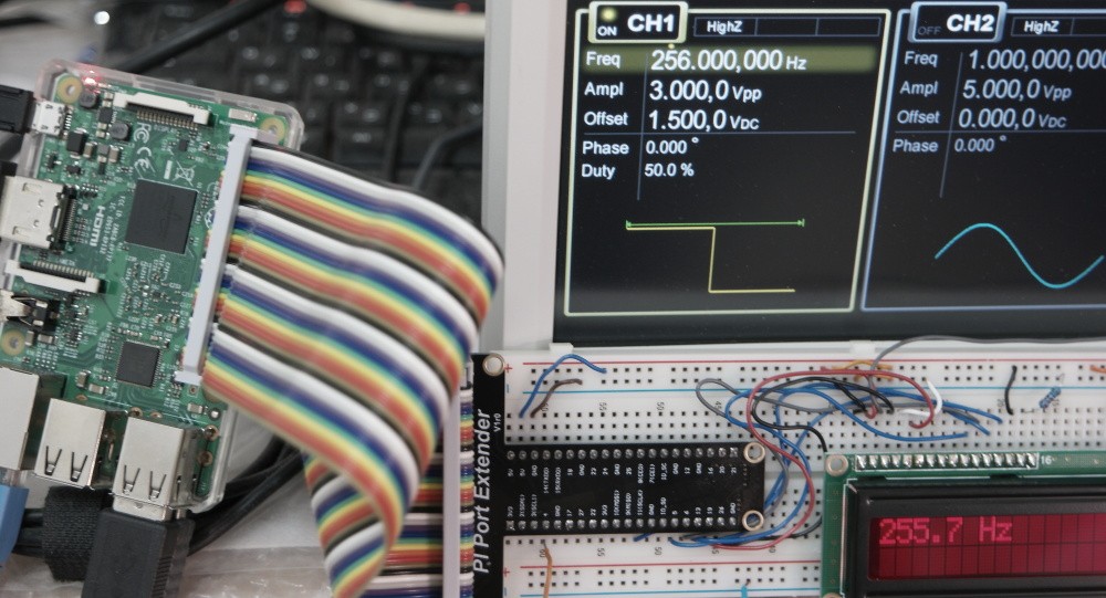
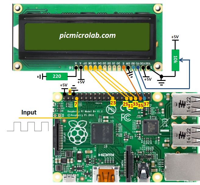
Basic Frequency Counter with Raspberry Pi can be built in less than 15 minutes and does not require any additional components. The input signal is a square wave with 3v amplitude connected to one of Raspberry I/O pins.Design schematic is shown next.
The attached python code measures the time difference between high and low signals state thus calculating a time period of a signal. Now we need to convert to a frequency by 1/period and send the result to 2×16 LCD display. Current prototype has its limitations. The MAX frequency it can measure is just 10Khz and only works correctly with symmetric square wave.
In order to measure additional wave forms like sine for example a zero crossing detection method should be implemented in the code. I’ve also changed the default I2C clock from 100Khz to 1.7Mhz in an attempt to capture higher frequency signals but above 10Khz the readings become unstable and do not reflect the correct frequency as can be shown in a short video attached below.