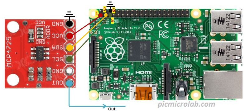
Generating Sine wave is a relatively simple task. It can be done by adding MCP4725 12bit DAC to Raspberry Pi. For Arduino version based on PCF8591 IC click this link. This setup is based on I2C interface and works by sending 2*Pi radian angle divided by 4096 to a sine function from math.py library. In response a sine function returns a calculated value. This value must be amplitude adjusted and normalized to fit 0-3.3V range and an offset is added to eliminate any negative values. So now a sine wave is riding a constant voltage of 1 Volts .This is a working setup and will produce sine wave as expected. Python example code can be downloaded here.
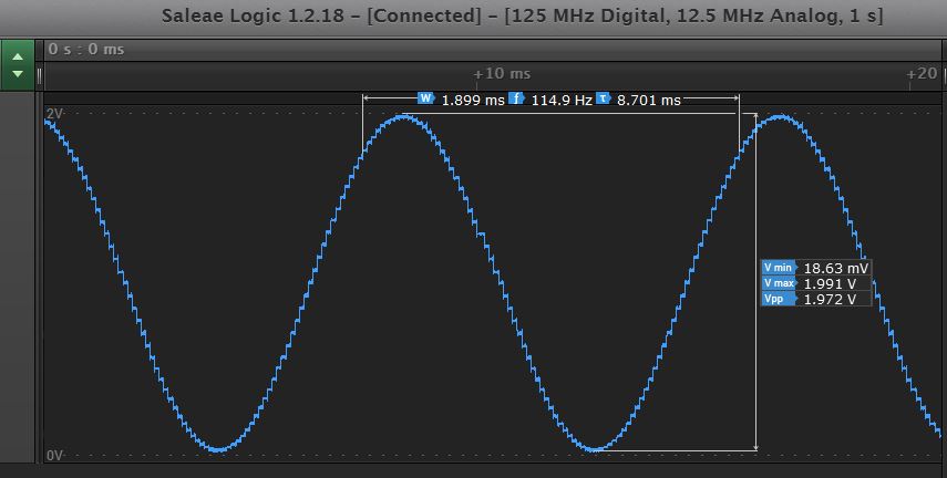
However the default SCL clock setting of 100Khz is too slow to output high enough frequencies. If you send an entire 4096 values to DAC you’ll get less than 10Hz frequency. One solution is to skip some values from sine function range instead of a full 2Pi/4095 angle. More advanced option is to configure I2C clock setting to a higher value by adding i2c_arm_baudrate=1700000 line to boot.txt file. The max speed I’ve managed to set was 1.7MHz despite the fact that a MCP4725 can work by itself up to 3.4MHz according to its datasheet. I recommend to start with lower setting of 400KHz to verify your Raspberry Pi can handle it and then increase the I2C speed. You can edit this file by using sudo nano /boot/config.txt command in a terminal window. Next I’ve added a screen capture of sine wave taken with Saleae Logic Pro 8 analyzer. It’s a very useful device and can help you to measure and debug your setup. As you can see 115Hz output frequency was achieved. By modifying the code additional signals can be generated like square, triangular or any other arbitrary wave.