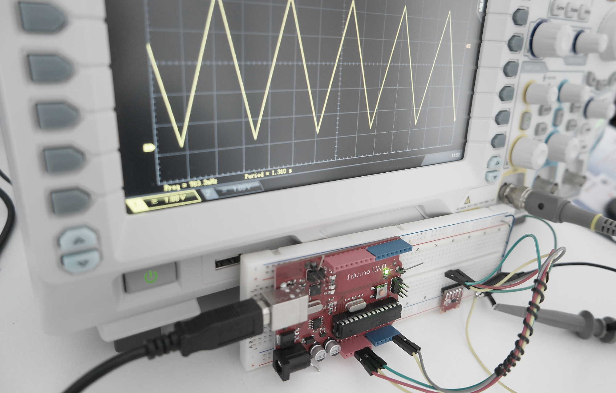
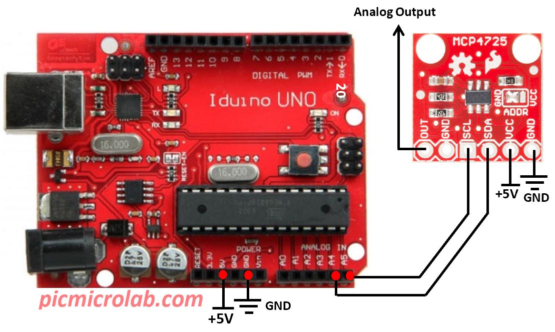
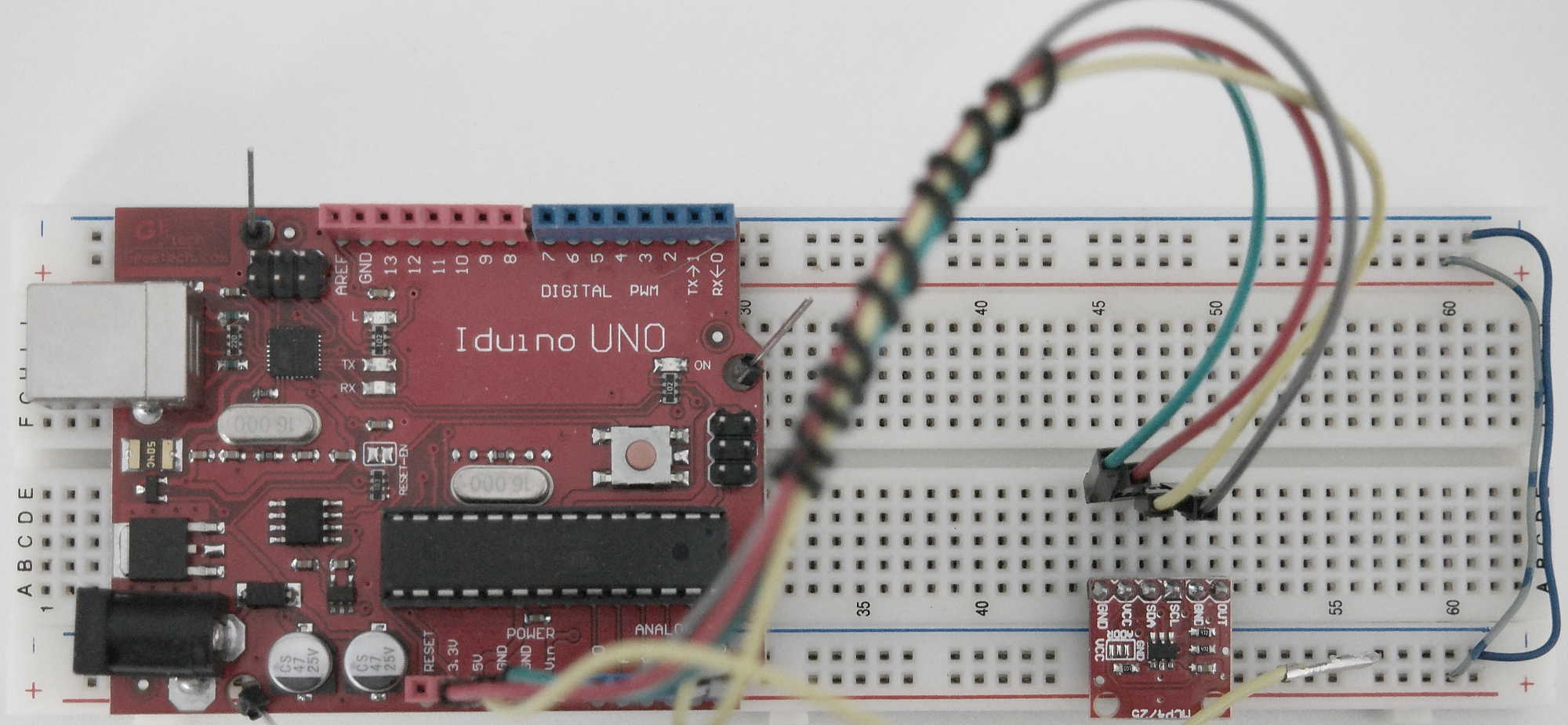
In this post I’ll show you how a 12 bit DAC model MCP4725 can be connected and controlled by Arduino or a compatible board. Similar design based on Raspberry Pi platform can be found at this link . Wire.h and Adafruit_MCP4725.h libraries were used in this design. Attached Arduino sketch generate a triangular wave just to demonstrate the functionality of the circuit. This is done by 2 loops. One is used to generate a rising slope by increasing the values being sent to DAC from 0 up to 4095 and the other for falling slope from 4095 to 0. The MCP4725 used I2C protocol with 100khz being a default clock setting for Arduino. In this case the resulting signal is extremely slow less than 1 Hz as can be seen from oscilloscope screen capture below. In the next figure a design schematic is shown.
I was trying to use Wire.setClock(400000) in order to produces a faster clock but it did not change the clock as I was expected. According to MCP4725 documentation it can operate with higher I2C clock so it may be the limitation of ATmega 328P chip or maybe I did not configure it correctly . Further investigation is needed. In any case reducing the number of values being sent to DAC will produce a faster signal. To make this project more interesting a basic keypad for example can be added to select the desired shape of the output signal.
By slightly modifying the attached code more complex patterns like an arbitrary or a sin wave can be achieved. Also a short video is available to show the actual generated waveform on the oscilloscope.