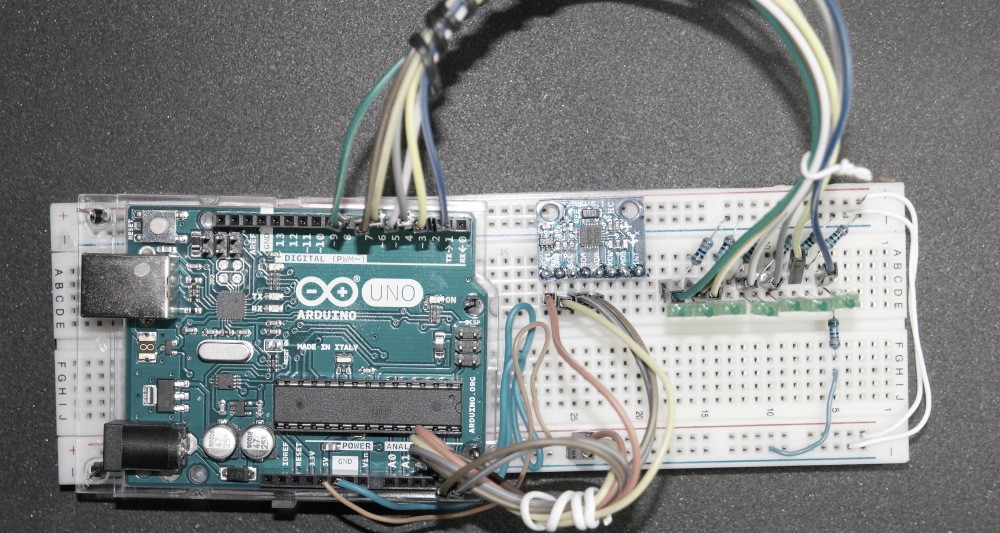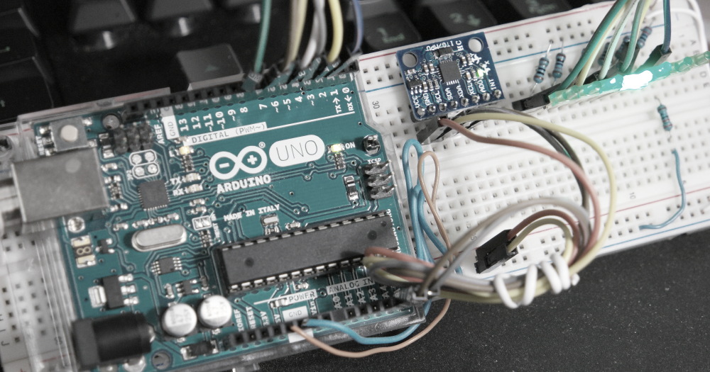
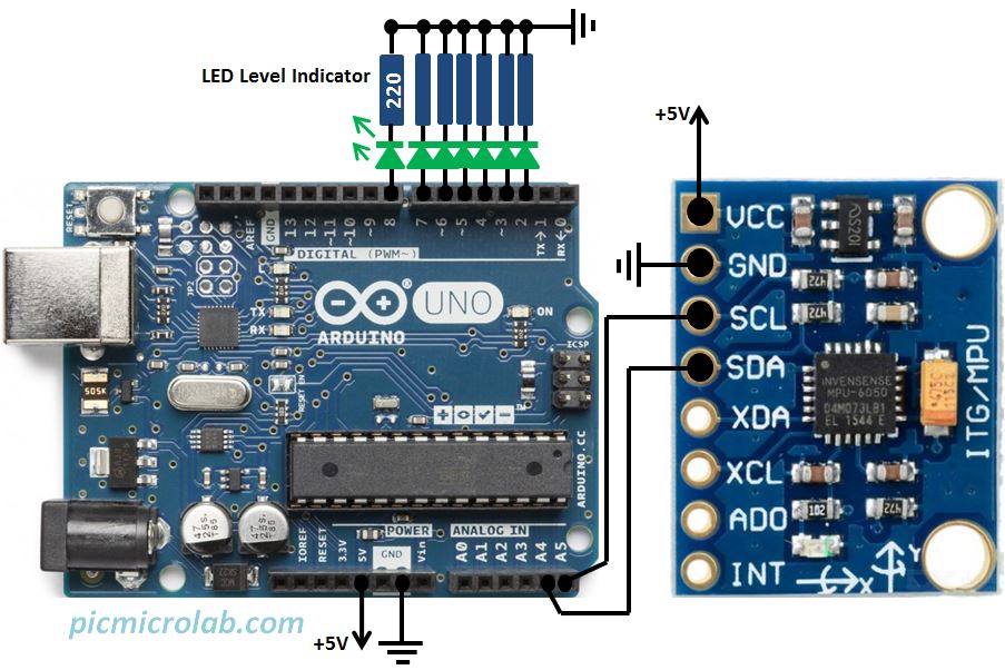
In this post a 1 axis basic digital level design will be presented. This circuit is based on Arduino UNO board and MPU6050 accelerometer and gyroscope chip. The communication is done using I2C interface. MPU6050 module address can vary depending on the board you are using. Usually these values are 0x68 or 0x69. RAW position data of y-axis from MPU6050 Module is divided into 6 segments and then sent to relevant LED. No additional calculations are done, it’s a very basic implementation. I was planning to at least make an average of multiple positions reading to smooth out some irregularities in the data but it looks like the circuit works OK. More details can be found in the attached Arduino sketch here. In the next figure a design schematic is shown.
Essentially the LED indicator is behaving like a level bubble moving from side to side according to a sensor position. Tilting the board will turn ON the corresponding LED as can be seen from a short video on the bottom of the page.