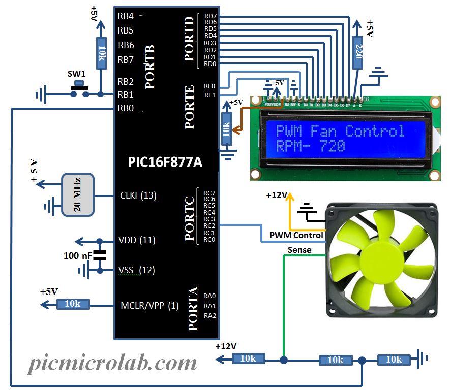
The schematic includes an LCD display for monitoring fan RPM however if you need a basic controller the LCD can be omitted thus reducing the size of the board. In this case only 2 components are needed, microcontroller and simple push button. If this post will generate enough interest I’ll try to fit the design into 8 pin MCU like PIC12F675
,I have a few available ICs. Currently only one fan can be controlled and monitored by PIC , however this limitation can be removed by implementing software PWM instead of using CCP module.
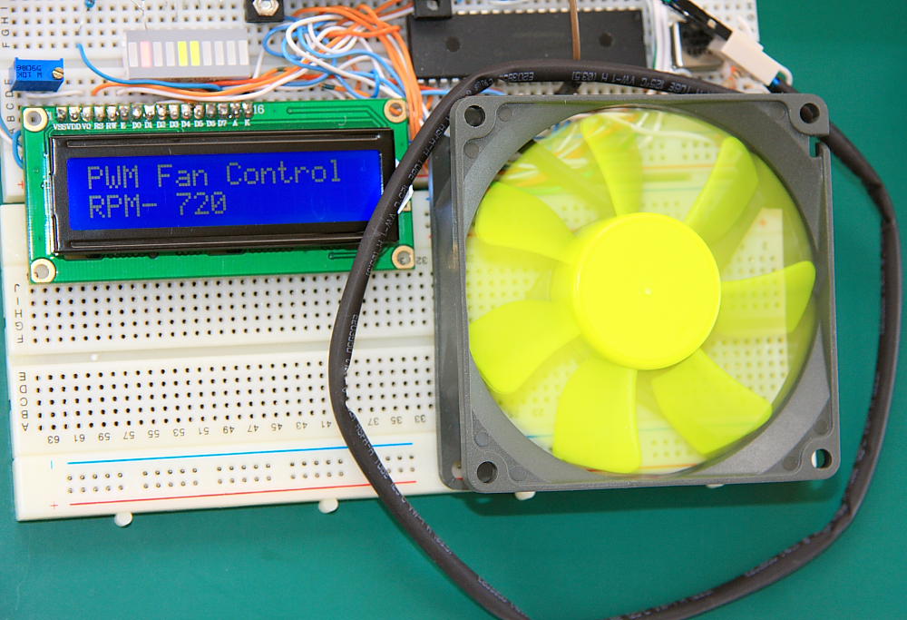
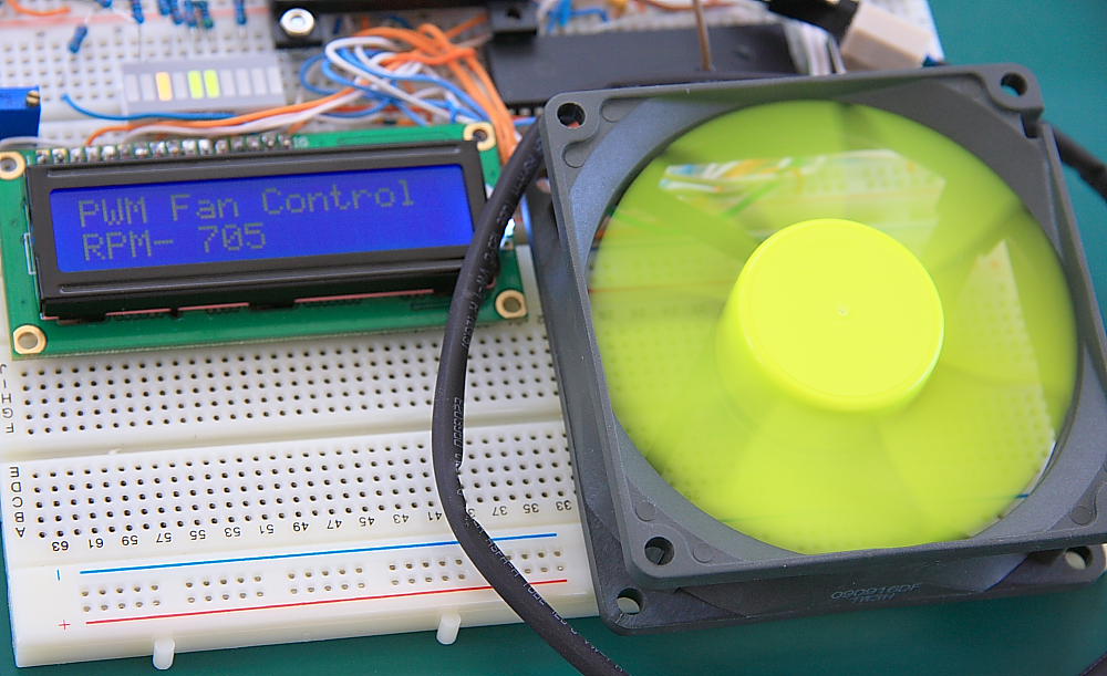
Fan RPM is shown on the LCD , update rate is 1 sec. Pressing SW1 (see schematic) will change the Fan speed. As with all other projects assembly source code is available at the bottom of the page. I’ve tried to add clear comments explaining each function. Basically 4 subroutines are used. One for calculating the Sense wire frequency, second function to translate from revolution per second to RPM. The third function converts the result to Unpacked BCD, and the last one to send the data to LCD display. Assembly/hex files available here. Here is a short video demonstrating PWM Fan controller operation.