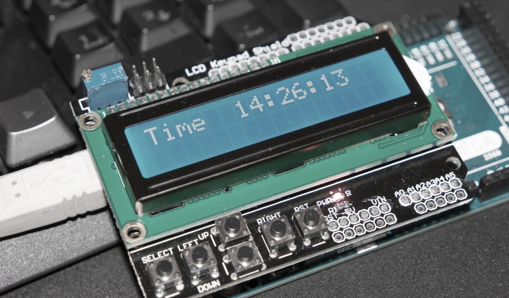
Arduino clock can be implemented by using LCD Shield Board for Arduino. This shield can simplify the prototyping process of many Arduino based circuits. It incorporates a 16×2 display and a basic 6 buttons keypad thus removing the need for additional wires and connections. All buttons are connected to A0 analog input through a resistor voltage divider. Pressing any buttons will result in different voltages being applied to the A0 input. By measuring this voltage with analogRead(A0) function we can differentiate what keypad button was pressed and control the code accordingly. Regarding the LCD display only a simple remapping of RS=8, EN=9, D4=4, D5=5, D6=6, D7=7 is required. After verifying that a shield was configured correctly we can write the clock code. 3 counters for hours, minutes and seconds make the clock program. What is left is just output the correct readings to the LCD and add the option for adjusting the time. More detailed information can be found in the attached sketch. In the next figure a design schematic is presented.
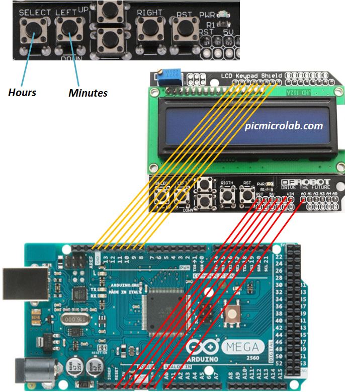
Not all connections are shown , just make sure that A0 pin is aligned with A0 on the Arduino MEGA board and it should work fine. I’ve also uploaded a short video showing clock operation.
Similar designs based on Arduino board and PIC micro-controller also available.