PWM Fan Controller

PWM Fan Controller Featured Image

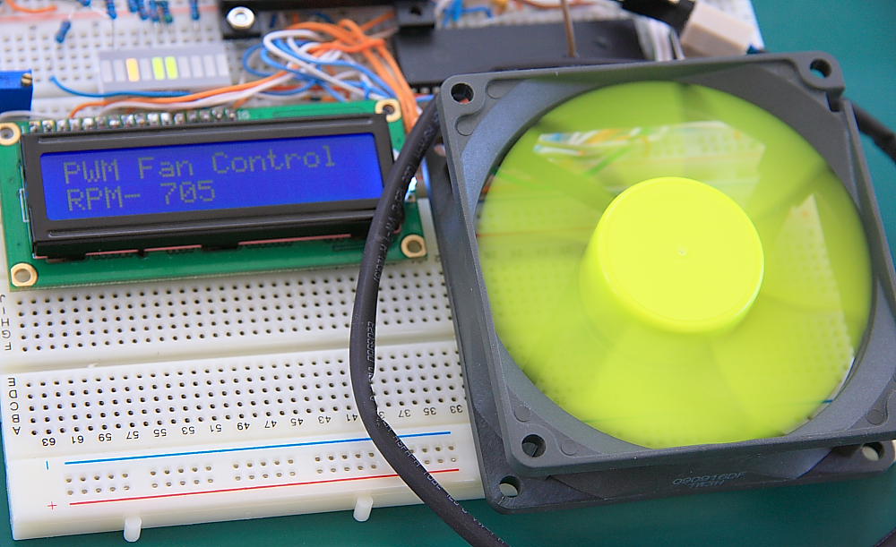
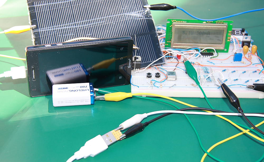
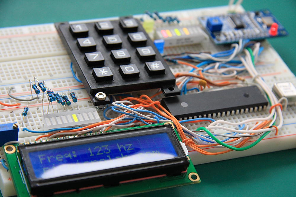
Pulse Width Modulation (PWM) is very common technique for controlling cooling fan speed in Desktop PC. In this project PIC16F877A based Pulse Width Modulation  controller was built and tested with 2 fans. 80 mm Coolink SWiF2-80P PWM Fan and Arctic Cooling F12 PWM 120 mm. These are 4 wire fans and their pinouts are shown in … Read more

Solar Power Mobile Charger

Solar Power Mobile Charger Featured Image

Solar power mobile charger can be built by tweaking digital power supply schematic. The Software/Hardware stayed almost the same as the original circuit.Current design has the same overcurrent protection and output voltage can be changed by pressing SW1. Voltage and Current are shown on LCD Display. The most obvious additions are Solar Panel and 9V 780 … Read more

AD9850 Signal Generator PIC16F

AD9850 Signal Generator Featured Image

This is a modified version of basic wave generator design with AD9850 and Microchip PIC16F microcontroller. A relatively simple assembly code available for download at the bottom of the page. Instead of using a rotary encoder as many other similar available designs a simple 3×4 Keypad was used to load the frequency value. The data is … Read more

10Bit 7-Segment Digital Voltmeter 0-24V

10 Bit 7-Segment Digital Voltmeter Featured Image

This is an upgrade to recently published Simple Digital Voltmeter.Few improvements were done to hardware and software.DVM operating range  was slightly increased up to 24 V Max, however the most significant change is that the code now uses full 10 bit of ADC resolution to calculate the voltage being measured allowing 3 Digit result  for 0-9.99 range  and 4 … Read more

Power Supply 2.5 – 12 V

Digital Power Supply Prototype Board

  Power Supply is probably the most common electronics project you can build.This is a basic design for digital power supply. It was built around 3 main components. Digital potentiometer – MCP4251-502E/P, Low  Dropout Voltage Regulator – MIC29152 and PIC16F877A.The idea behind it is simple. Take a standard LDO design – 2 resistors, first resistor … Read more