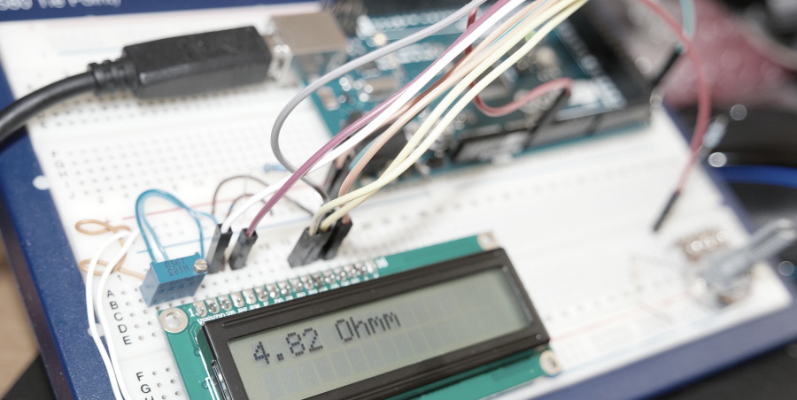
Arduino Ohm Meter is one of the simplest circuits that can be built with minimal number of required components. As can be seen from design schematic a standard 2×16 LCD display and 3 resistors are all you need to complete this project. The value of unknown resistor marked with ? will be shown on the upper left corner of the display.
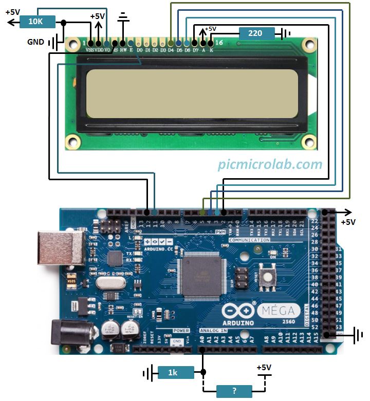
The Arduino code for this project is also very basic. Essentially it uses a formula derived from a voltage divider calculation to find an unknown resistor value. Use of high precision 1k resistor is recommended for better accuracy. I’ve tested this circuit by measuring resistors up to 1Mohm, however above 100k the reading become inaccurate. It happens because high resistor value causes only a very small portion of the voltage to drop on a reference resistor.
One possible solution to get a more precise measurement is to select different values of a reference resistor for desired measurement range. This can be done with an analog switch IC like 4066 similar to auto range feature in most modern DVM. In this case additional Arduino I/O lines will be needed to control the switch.I’m planning to adapt this design for other popular platforms like PIC16F MCU and Raspberry Pi. A short video demonstrating a working prototype is shown next.