In this article I’m going to show you how an 8×8 LED Dot Matrix Display can be driven by MAX7219 with Arduino.There are 2 similar designs. PIC16F876 version is available at this link ,for circuit based on 74HC595 click here.For this project I’ve created my own function to send data to MAX7219.This function is called SendDataDotMatrix(). It accepts a desired digit value and uses a multiplexing routine to turn ON relevant Dot Matrix Display columns and rows. Current set up just cycles through available display characters 0-9 and A-F with 1 sec delay. More information is available in the design sketch here. As you can see from schematic diagram the wiring is not too complicated.
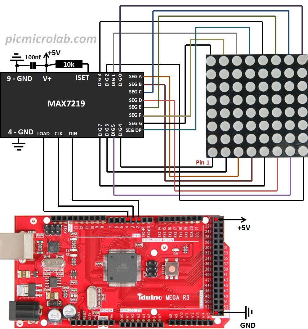
The columns and rows connections were not chosen randomly, instead I’ve duplicated the connections of popular Dot Matrix display modules like this one with built in MAX7219 chip. In this case it has 4 Digit Display but the structure is the same. Keep the wires between Arduino board and the module as short as possible and add a capacitor between positive supply and GND as close as possible to V+,GND of MAX7219 IC, otherwise the chip can misbehave.
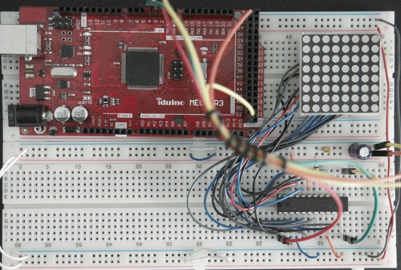
In case of MAX7219 lock up – all dots are ON try to reset the Arduino board or power cycle the circuit. Next is a short video showing my prototype.