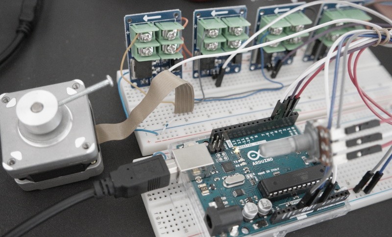
Basic Stepper Motor Controller can be built with Arduino board and a few additional components like MOSFET switches and a potentiometer to control unipolar stepper motor speed and direction. The principle of operation is relatively simple. When a potentiometer is in the middle position meaning about 2.5 Volts supplied to analog input A0 the motor is idle. Turning the potentiometer left rotates the motor CCW with 3 different speed settings. Likewise turning the potentiometer right rotates the motor CW. For MAX speed rotate fully left or right. Schematic diagram is shown next.
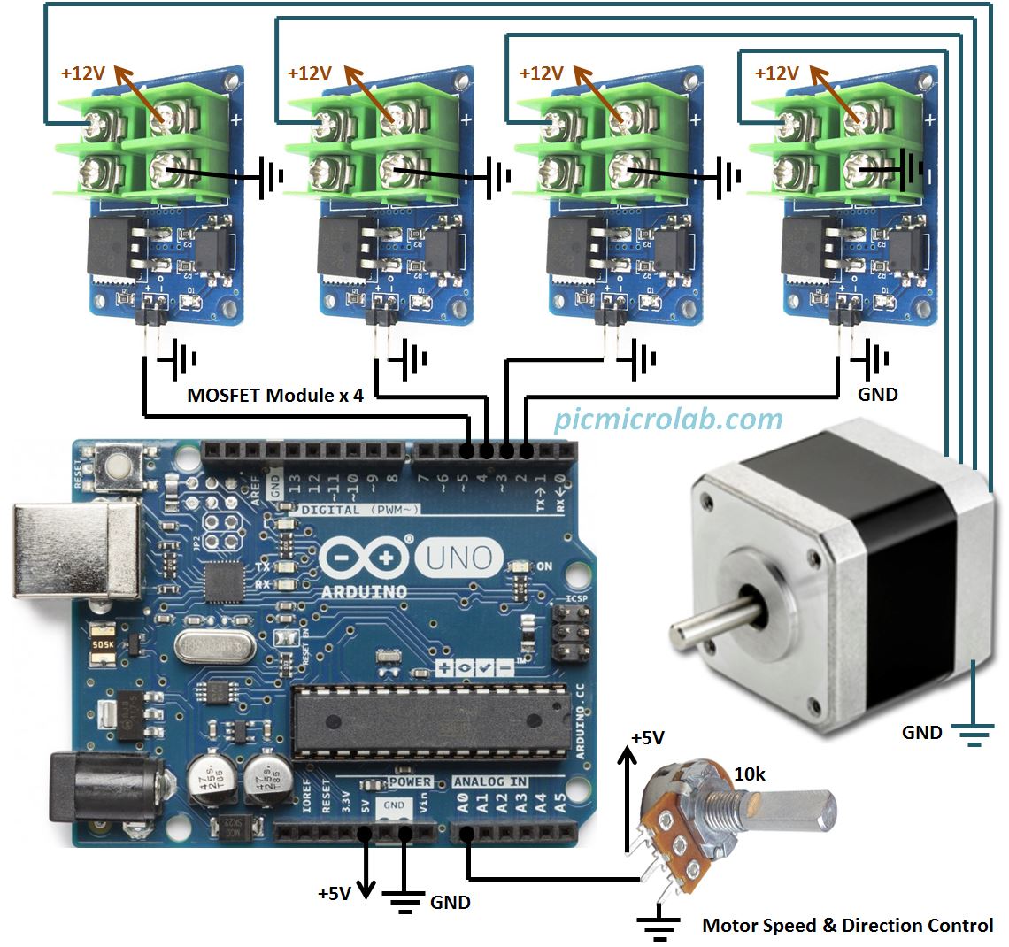
I’ve implemented only 3 motor speed settings by dividing the input voltage to a number of ranges. The attached Arduino sketch constantly checks the input voltage and decides what direction the step motor should turn and how fast. If you want to achieve a more gradual transition in stepper rotation just increase the number of these ranges and assign a different rotation speed to each one by changing the delay between motor coils switching sequence. This prototype was tested on Arduino UNO board and should also work on all compatible devices. If you don’t have the same MOSFET switches you can probably replace them with ULN2003A chip. I’ve previously published similar design based on PIC16F877 MCU and used ULN2003A to drive the motor. Next you can see a short video showing the circuit operation.