In this post a simple Digital Dual Voltmeter and Ampere meter design will be shown. It uses PIC16F876A microcontroller and 2×16 LCD display
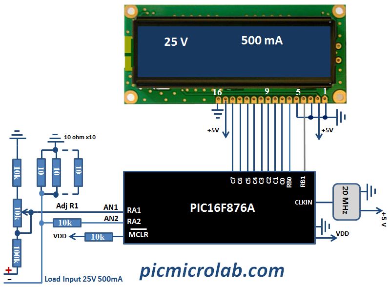
and has 2 input channels for measuring voltage in 0-25v range and current up to 500mA. The task of measuring voltage/current values is very common one and was covered in a number of recently published articles like Simple Digital Voltmeter and 10Bit 7-Segment Voltmeter. All these circuits share a similar design and most of assembly subroutines in the source code are identical. I recommend reviewing these posts for additional information. Circuit operation can be summarized in two following sentences. Microcontroller ADC converter samples input voltage on two channels through a voltage divider. These values are converted to BCD format, normalized for required range and sent to LCD display. As usual for more detailed explanation please see attached assembly source file at the bottom of the page. In the next figure you can see design schematic.
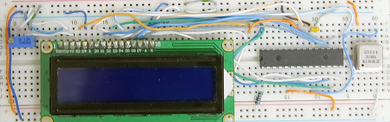
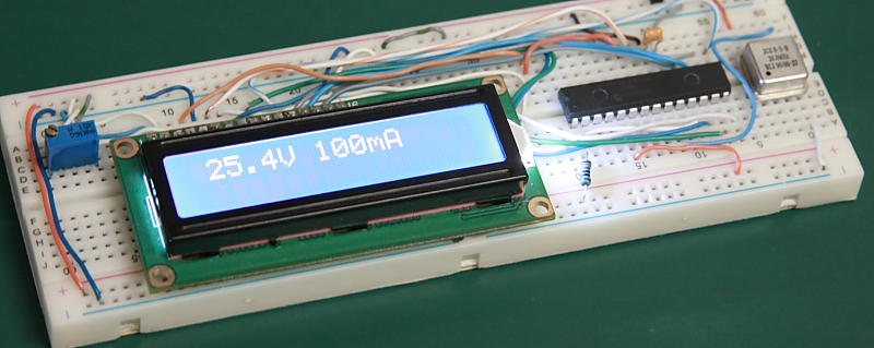
Circuit prototype board is shown next. A simple voltage regulator like 7805 can be used as power supply however it’s omitted from schematic and the breadboard. Assembly source code is available here.