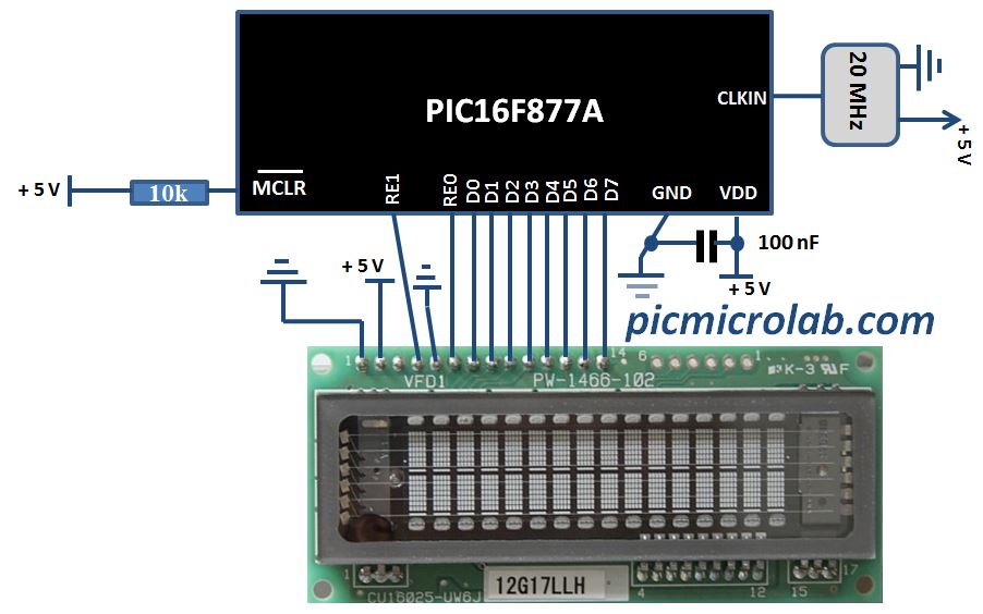
Vacuum fluorescent display can be a good alternative to a Liquid-crystal displays in some applications. They have a number of advantages over LCD like extended temperature range and excellent contrast in high brightness environment. The main disadvantage is higher power consumption making them less attractive in battery operated devices. In this post I’ll show you how you can use this type of display with microcontroller. You can purchase them on Ebay as I did here.CU16025 VFD module was used for this purpose as a direct replacement for 2×16 LCD display. Although the manufacturer of these modules provides some code examples I’ve used my own driver code (originally written for a LCD) and a parallel 8 bit connection to interface this display with PIC16F877A microcontroller. I’ve adapted assembly language subroutine that I wrote earlier for VFD module initialization and for sending data/command. The code was written in C in MPLAB X using XC8 compiler. The same subroutine was also used in VFD Voltmeter project. Use In-Circuit Debugger like PICkit 3 to program your target device. As you can see from the schematic below 2 PORTs were used to control the display. PORTD for data/command and PORTE for RS and Enable lines.
The code consist of 3 main functions: Display initialization, WriteDataVFD , WriteCommandVFD. Command for example can be an address of one of the segments and data is the character you want to display in ASCII. Comments in the source code should provide you with more detailed explanation on each instruction. Click here to download the code.