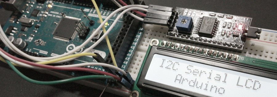
In this post I’m going to show you how to use a Serial I2C Interface Module to control 2×16 LCD display with Arduino. For similar design using PIC16F876 click this link. Instead of using 8 or 4 bit parallel connection from Arduino board to LCD only 2 pins are required. One for sending the Data (SDA) and the other is Clock (SCL). If your application needs a lot of I/O’s this module can be very useful. Serial I2C Interface Module is based on PCF8574 8-Bit I/O Expander chip with I2C capabilities. Potentiometer for controlling the LCD backlight is also located on the module printed circuit board. The schematic I’ve used for this circuit is shown next.
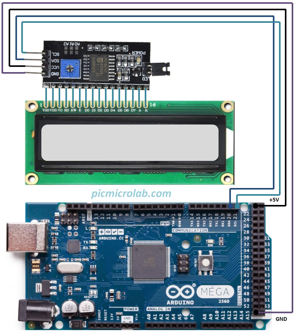
SDA,SCL pins are located in different places on Arduino UNO and MEGA boards. For Arduino MEGA – SDA (Pin 20),SCL (Pin 21). For Arduino UNO – SDA (A4),SCL (A5). More details on Arduino wire page. Now a few words about the code. I have used 2 libraries for this design. Wire.h and LiquidCrystal_I2C.h.These libraries not included in a standard Arduino IDE. You’ll need to add them in Sketch–>Include Library. Also in order to communicate with PCF8574 you need to provide a correct address. See how it’s done in the attached code here.
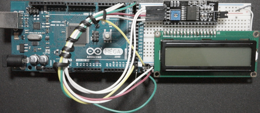
In some forums 0x20 or 0x27 was suggested as the module address. However it was not working for me. So I’ve used a simple loop with delay to scan for correct address. Basically after connecting the I2C module to Arduino you start sending a new address until the LCD responds. After a few tries 0x3f seems to work OK with this module. This simple design was tested on Arduino MEGA board and should work on other compatible devises.