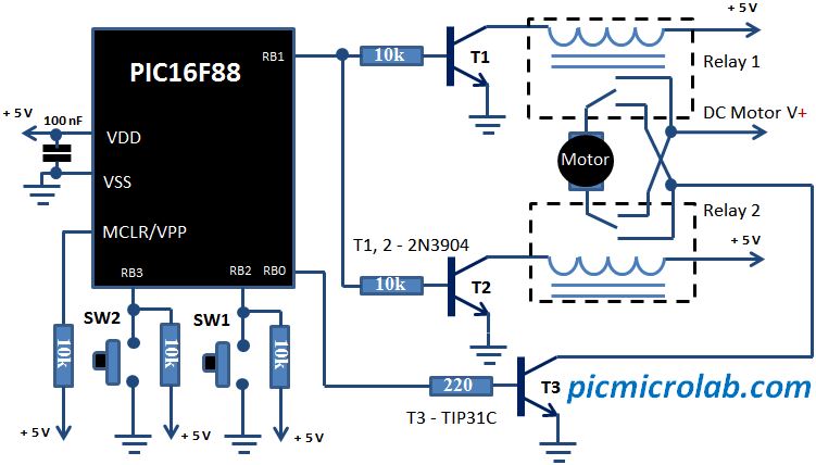
This post is about building a simple PIC16F88 based DC motor controller. Motor speed and direction can be controlled by two push buttons SW1, SW2. One for motor speed and the other for polarity. This post follows recently published projects like PWM Fan Controller and 2 Channel PC Fan Controller that share a similar design. Instead of using LM317 as output stage a microcontroller PWM output will be driving a medium power NPN transistor TIP31C
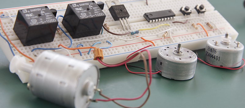
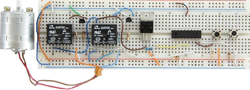
to control the motor, this makes a simpler driver. Although a relay with two contact pairs required for motor direction control it can be replaced with 2 simpler more common and cheaper SRD-S-105D
or similar 5V relays with only one contact group as was implemented in current design.
Briefly about circuit operation. Press SW1 to change the motor speed by modifying output signal duty cycle thus creating variable output voltage. Press SW2 to change motor direction, see attached assembly source code for more info at the bottom of this page. Here is the design schematic, as you can see it’s relatively simple. MCU, 3 transistors and a relay will do the job. No external clock source is needed as PIC16F88 has internal oscillator.
Design assembly source code is available here. See a short video demonstrating circuit operation.