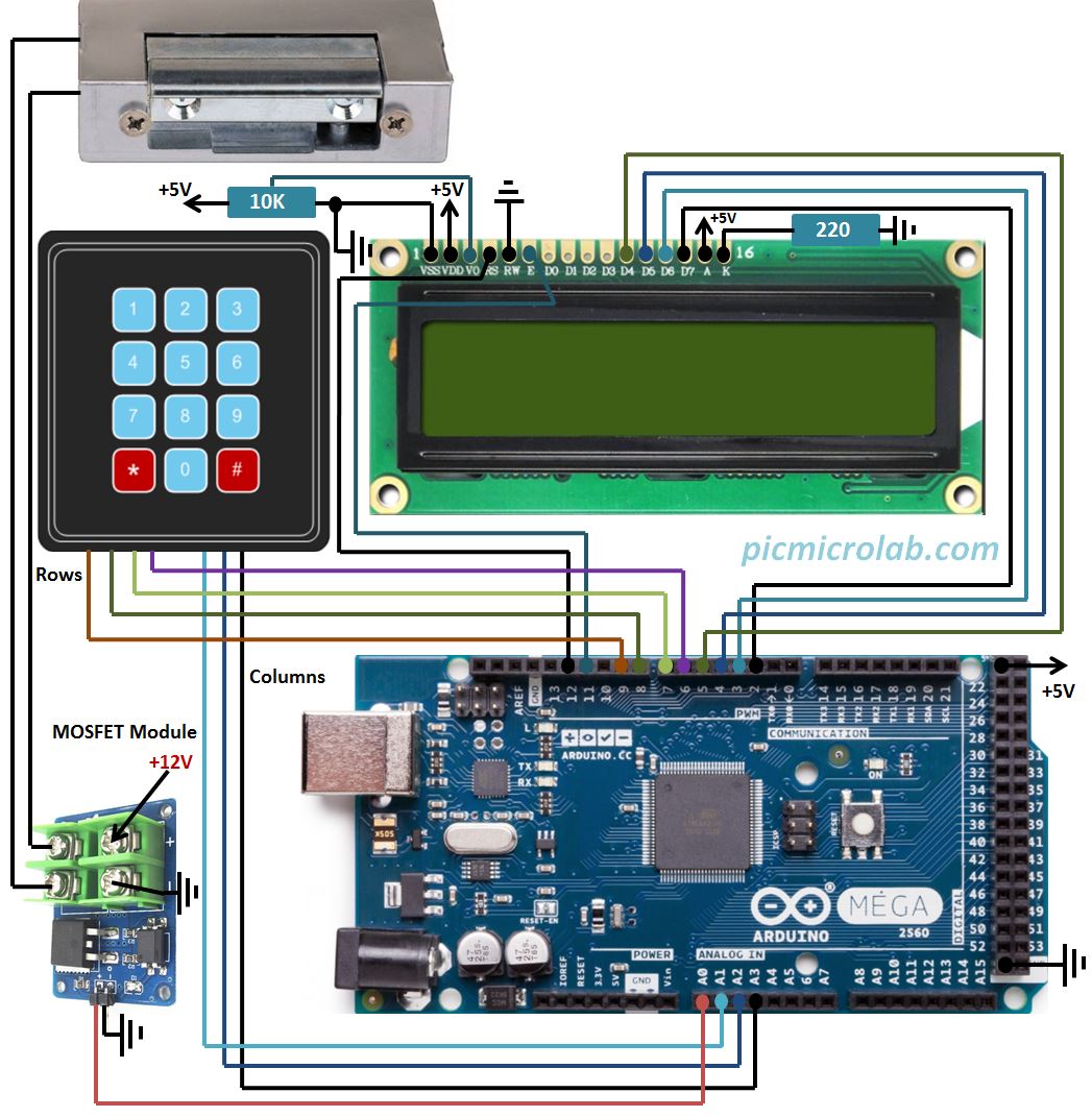
Here is another Arduino based design and this time I’ll show you how a 4-Digit Code Electronic Lock can be built with Arduino Mega or compatible boards. For similar design based on PIC16F877 click this link. The I/O I’ve used for this project are common for both Arduino Mega and Arduino UNO boards so this design should work on both platforms however I’ve tested only on Arduino Mega. As can be seen from design schematic diagram you’ll need the following components: 2×16 LCD Display – it just shows * as each code digit is entered. 4×3 – Keypad, I’ve used membrane matrix keypad to input the 4 digit code and a MOSFET module to drive the electric strike or electromagnetic lock. There are a lot of these modules available but I recommend using one with optocoupler to isolate Arduino board from high voltages/currents. And finally a 12 volt DC electric strike. Electronic Lock sketch can be downloaded here.
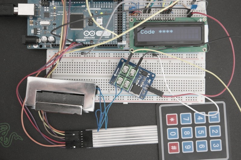
This circuit waits for 4 digit code to be entered by 4×3 keypad. Then it compares the received code to the code stored in Arduino sketch under Default Code Digits Settings and if there is a match it will send a 5v to A0 output for 5 seconds to open the lock.The default code is 3696
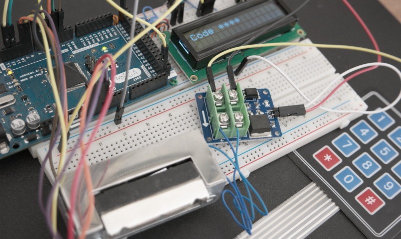
I’ve noticed that sometimes the entered digits are not received by circuit from the first try and you need to repeat the process. It may be the faulty keypad or not enough delay between keypad scans to avoid contact bouncing. Anyway here is a short video demonstrating how electronic lock prototype works.