Basically now 10 bits of ADC are multiplied by 4 to achieve 4096 V reading as a full scale and again by 8 to offset constant resistor 1:8 Voltage Divider at the input. Next the result is converted to unpacked BCD digits and sent to 7-Segment Display. Due to second multiplication by 8 the last digit is not displayed but can be easily recovered if needed. In order to get a good measuring result pay attention to power supply especially to filtering capacitors connected to voltage regulator like 7805 or LM317
. The fact that voltage regulator is used doesn’t necessary mean that you have a stable and low noise power. 22 uF tantalum capacitors
were used at input/output of 7805. More information on the next page.
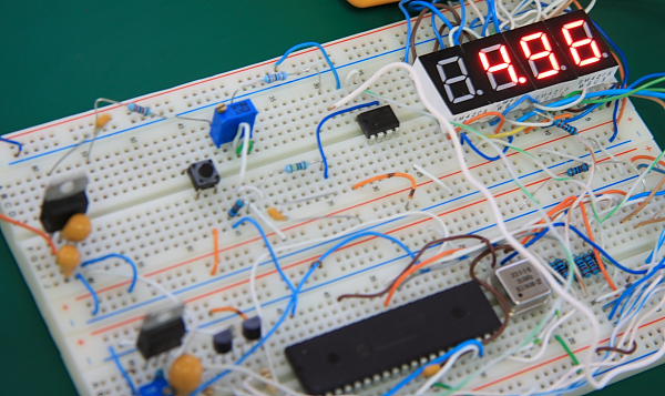
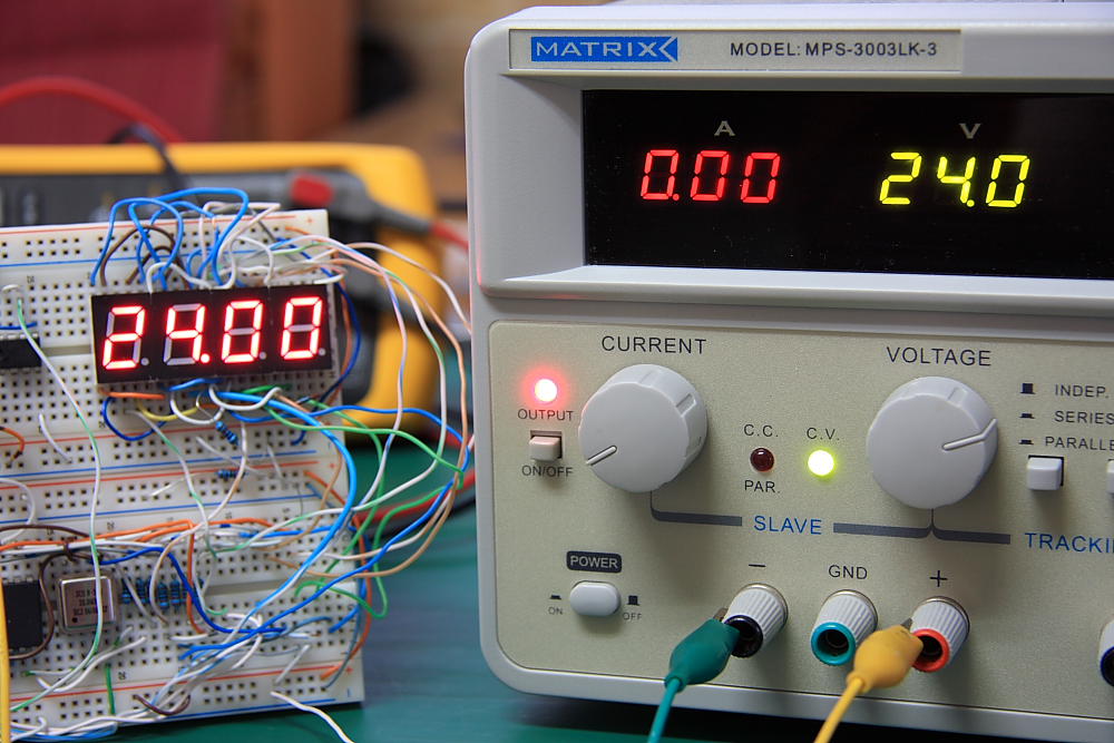
Tip for using Generic 7-Segment: Usually datasheet for generic parts can be difficult to find. For this project we need to know where the segment inputs are located. This can be done by using a Diode DVM function. Just connect one of DVM wires to arbitrary chosen 7-Segment pin and cycle through remaining pins until the segment is ON. Do it for additional few segments and you’ll know where the Common and individual pins are located. Max voltage reading test was done with DC Power Supply. Voltage above 24 V will not be displayed correctly.
As future improvement auto range capability can be added. Constant resistor divider can be replaced by a digital switch like CD4066 to select required division: 1:2, 1:4, 1:16, 1:32. In this case 4 digit full scale can be used for lower 2 ranges as long as the LSB digit is giving you a stable reading.Assembly code can be downloaded here. More advanced version of this project is available here.