


In this post I’d like to share a design of PWM Fan controller based on PIC16F684
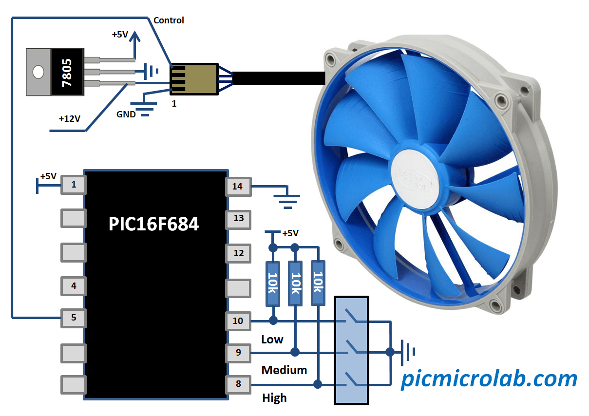


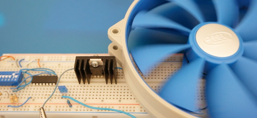
Prototype was tested on DeepCool 140mm UF140 PWM Fan
LIST P=PIC16F684
include <P16f684.inc>
__CONFIG _CP_OFF & _WDT_OFF & _BOD_OFF & _PWRTE_OFF & _INTRC_OSC_NOCLKOUT & _CPD_OFF
org 0x00
nop
goto start
org 0x10
start: bcf STATUS,RP0
bcf STATUS,RP1
CLRF T2CON
BSF T2CON,0x0
CLRF CCP1CON ;CCP module OFF
CLRF TMR2 ;Clear Timer2
;——————————————————-
bsf STATUS,RP0
bcf STATUS,RP1
bsf TRISC,0x00 ;Bits 0,1,2 are Inputs
bsf TRISC,0x01
bsf TRISC,0x02
clrf ANSEL ;All ports are Digital
bcf STATUS,RP0
movlw 0x07
movwf CMCON0 ;All ports are Digital
;——————————————————-
loop: MOVLW 0x30 ;Default is High Speed
btfss PORTC,0x00 ;High Fan Speed
MOVLW 0x30
btfss PORTC,0x01 ;Medium Fan Speed
MOVLW 0x15
btfss PORTC,0x02 ;Low Fan Speed
MOVLW 0x10
;——————————————————-
;MOVLW 0x20;0x03 ;0x30 – Duty 97%; 0x01 – Duty < 2%
;High – 0x30 Medium – 0x20 Low – 0x10
PWM: MOVWF CCPR1L ;Duty Cycle
CLRF INTCON ;Disable interrupts, clear T0IF
BSF STATUS,RP0 ;Bank1
MOVLW 0x30;0x09 ;PWM period is 10*4Tosc
MOVWF PR2
BCF TRISC,0x05 ;Make pin 5 Output
CLRF PIE1 ;Disable peripheral interrupts
BCF STATUS,RP0 ;Bank0
CLRF PIR1
MOVLW 0x0C ;PWM mode,2 LSB bits of Duty Cycle=10
MOVWF CCP1CON ;Duty Cycle=1010 =10Tosc
BSF T2CON,TMR2ON;Timer2 starts to increment
GOTO loop
end
On the next page you can get the code and see a short video.
Source code and a compiled HEX file can be downloaded here. Now let’s see how this circuit actually works.If you look closely you’ll notice that fan speed changes according to DIP switch position.The default speed setting is High. You can also connect a DVM at the PWM output of the microcontroller and verify that changing duty cycle causes the average voltage to vary from around 1.9 V to 5V.
