Site icon Microcontroller Based Projects

AD9850 Signal Generator PIC16F

AD9850 Signal Generator Featured Image

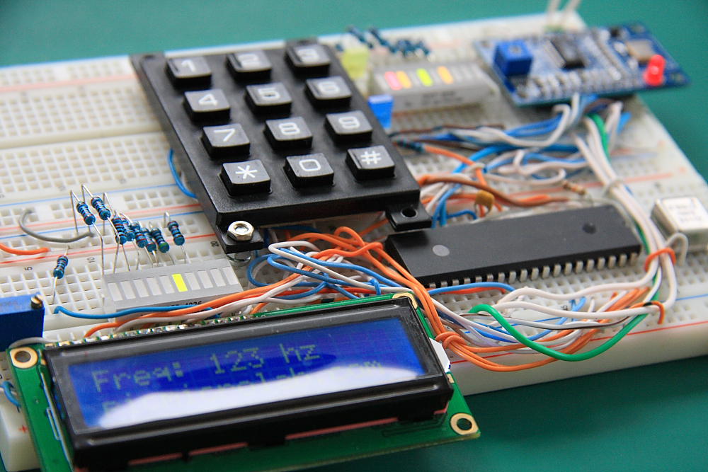
This is a modified version of basic wave generator design with AD9850 and Microchip PIC16F microcontroller. A relatively simple assembly code available for download at the bottom of the page. Instead of using a rotary encoder as many other similar available designs a simple 3×4 Keypad was used to load the frequency value. The data is displayed on a standard 2×16 LCD module .At this time frequency range is limited to 0-999Khz due to software issues. The code needs some more work as it currently does not support MHz range and small frequency deviations were observed between the desired value and produced frequency.(1-2 Hz for 0-999 Hz range and 1-2 KHz for 0-999Khz).


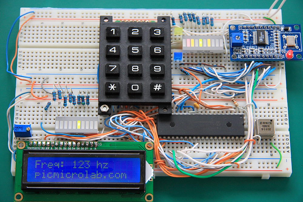
In order to get a  frequency  you’ll need to enter a 3 digit number. For example for 123 Hz enter 1, 2, and 3.For 5Hz enter 0, 0, and 5. Select the range by pressing “*” key – it will cycle trough Hz, KHz and MHz ranges (MHz – not implemented yet).Press “#” to load the number into AD9850.Parallel load sequence was used. For more details click here. Now a Sine or a Square waves with desired frequency available at generator outputs. Here is the full design schematic.

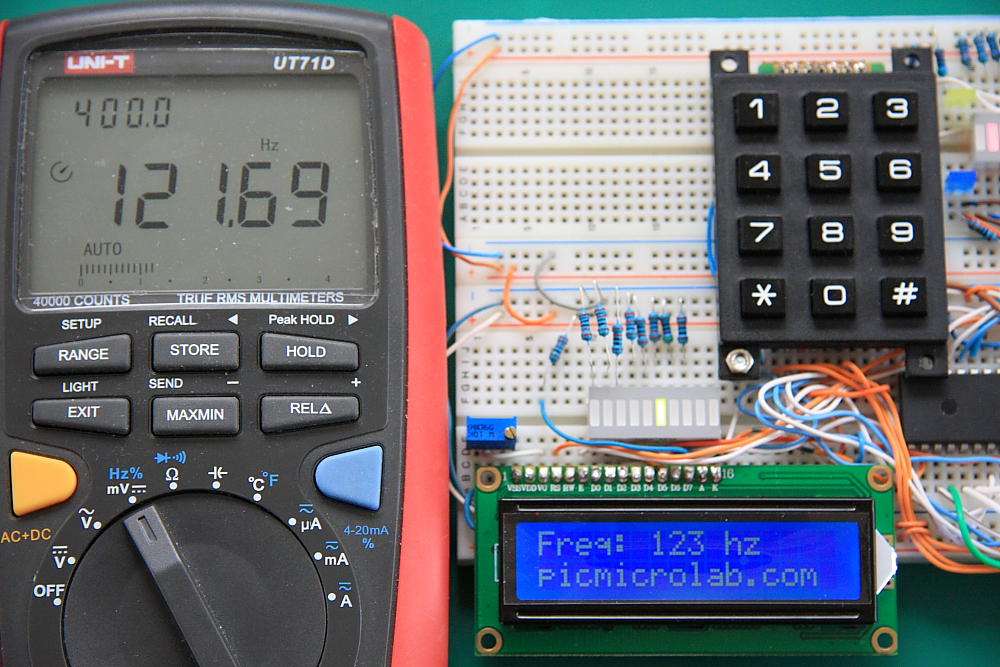
Generated frequency measured by UT71D DVM.

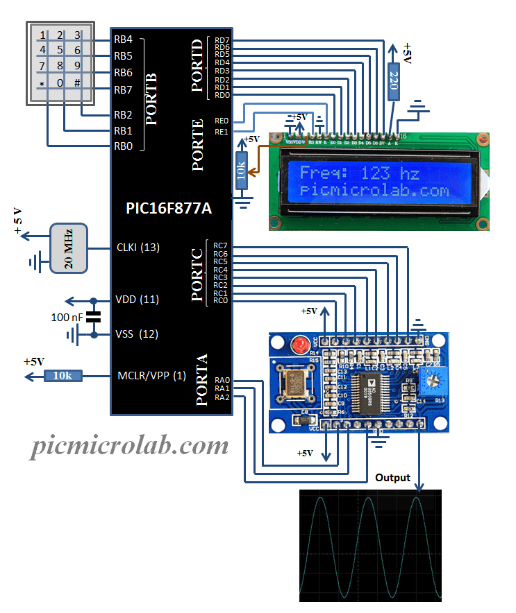
More about the code. PIC  is constantly searching the keypad. As soon as 3 digit numbers are entered they are converted to binary by BCD to binary routine and then multiplied by a range constant to produce a valid frequency word for AD9850.Another routine is used to sends the data to LCD. Assembly/hex files are here.

Exit mobile version