


A simple wave generator should be a part of every electronics enthusiast toolset. Basic Sine/Square output in reasonable frequency range will be sufficient for general use. Luckily such generators are available in form of a very popular AD9850 module

The code was written for PIC16F876A, however it should work on all similar MCU.As you can see in the design schematic 11 I/O are required: 8 bits of PORTC are used as Data and 3 bits of PORTA are controlling the parallel loading W_CLK, FU_UD and Reset of AD9850.Here is the parallel load timing sequence as provided by IC manufacturer Analog Devices.
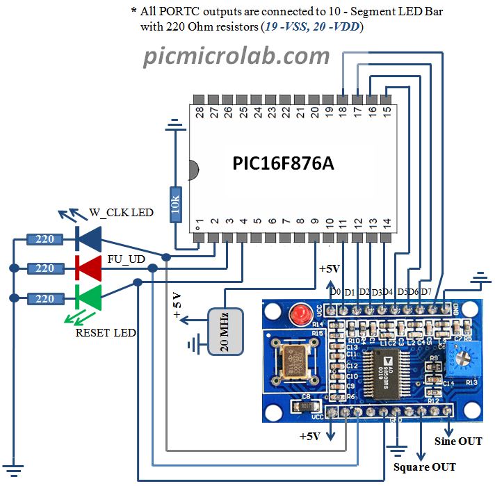
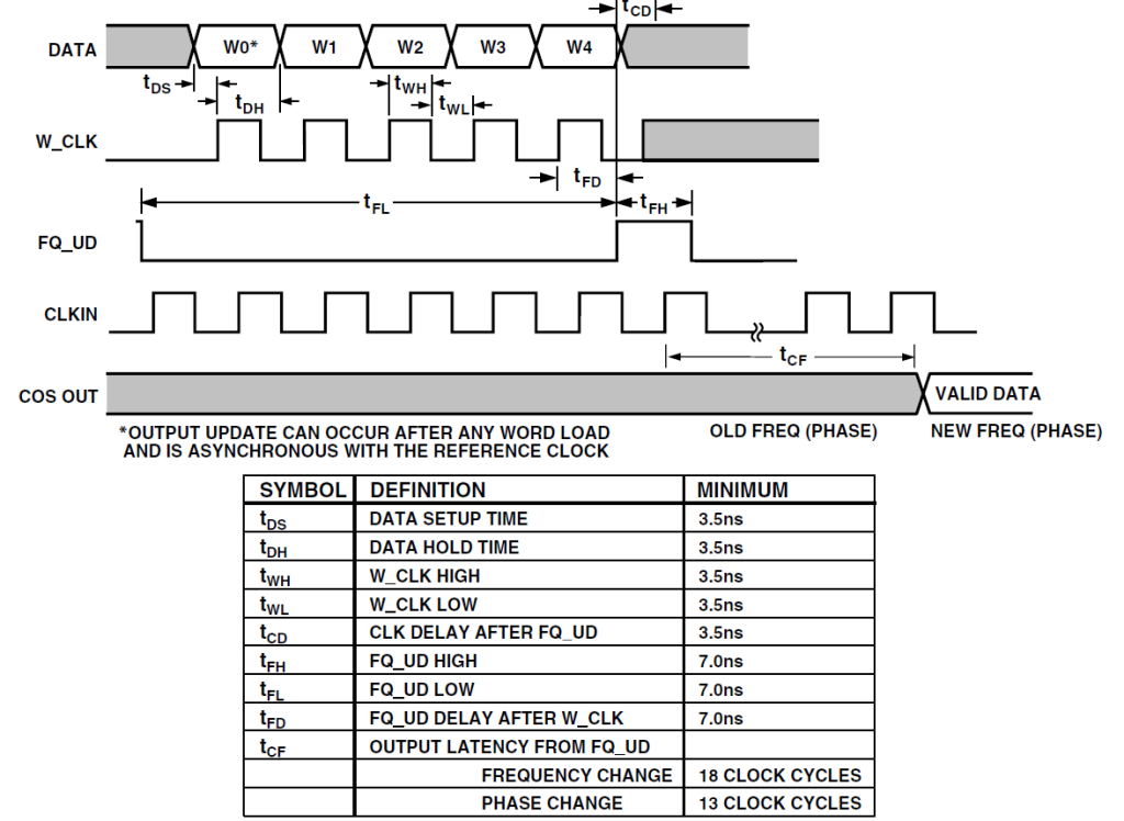
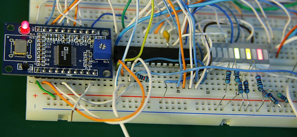
Full data sheet can be downloaded here. Minimum time delay should not be a problem as PIC port switching time is much slower. Also a big delay was intentionally put in the code, about 0.5 s to give enough time to see signals flow.The delay can be reduced to a minimum if all works well. If you’ve followed the schematic and used the same code you’ll see the following sequence as soon as PIC is released from Reset state:
-
Line RA2 will reset the AD9850,Reset LED ON for 0.5s and OFF.
-
First 8 bit Word out of 5 Words will be sent by PIC to PORTC. Bit RA0 will toggle W_CLK line to load the Word into AD9850.
-
Additional 4 parallel loads will be done. After loading 5 words RA1 will toggle FU_UD.
Shortly after you can see an output available on AD9850 representing the 5 words frequency value. Actually only 4 words represent the frequency, first byte in parallel load is Phase and 2 control bits.
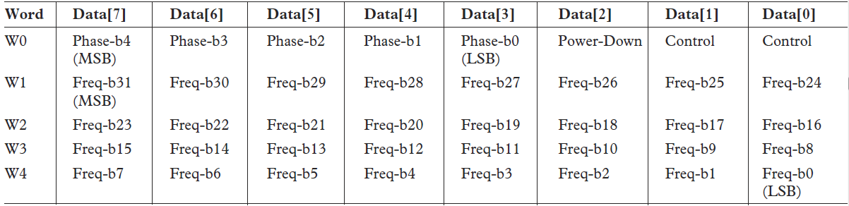
Analog Devices also offers an online calculator for proper word value for each frequency. For AD9850 with 125 MHz oscillator and 8.1Khz output the 32 bit Word in hex is 00043F2A. 00 is Word 1 ,04 – Word 2, 3F – Word 3, 2A – Word 4.What about Word 0 ? At least in the beginning you probably don’t need a Phase change so leave it at 0.The full 40 bit Word looks like this
Word 0 – 0x00 MSB (Send first)
Word 1 – 0x00
Word 2 – 0x04
Word 3 – 0x3F
Word 4 – 0x2A
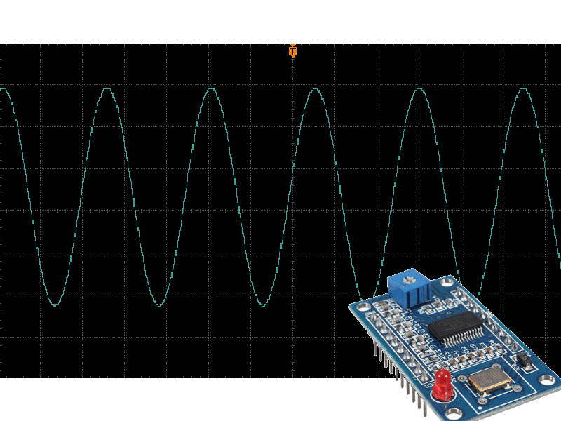
Attached code does exactly the same sequence as described above producing 8.1 KHz output. See DS2072
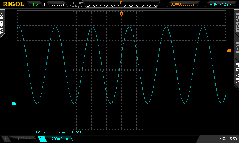
Sine wave is shown, however AD9850 also has square wave output with same frequency. Change the 4 Words being sent for other frequencies. Word of advice about square wave output. Square wave is produced by AD9850 module