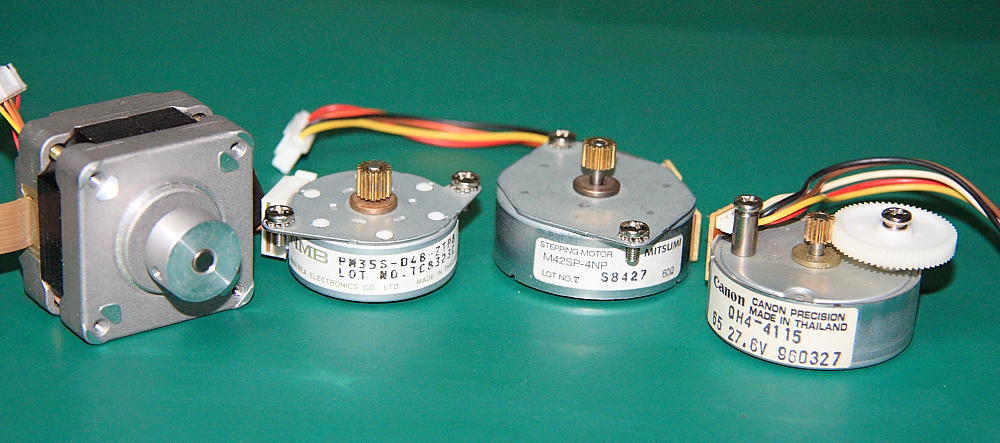
This article shows a basic interface between PIC16F microcontroller and a unipolar stepping motor using an assembly code. For programming the MCU you’ll need PICKIT2 or PICKIT3 device. Similar design for Arduino platform can be found at this link. Instead of using a dedicated motor driver IC like a very popular L293D ULN2003A was used. Just 4 I/O Pins are required to drive each coil of the motor. By energizing each coil in a particular sequence you can control the speed and direction of the motor. 4 lower bits of PORTC are used for controlling the step motor behavior. Triple nested loop is used to delay motor winding switching to about 200ms. You can experiment with changing the delay values for higher/lower speed but not too much, otherwise the motor may “stall”. I’ve modified a Solar Power Charger design by adding to it a tracking capabilities using 2 stepping motors as described below so it can follow the sun. Current project is a good starting point for testing various designs and interfacing techniques. I’ve tested 4 different unipolar step motors (5 wires), see attached schematic and pin out for each motor, these motors were dismantled from old printers and scanners.
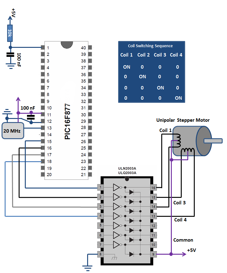
So now we’ll need to identify the individual coils and common connection of the motor. Use your DVM to measure resistance between pairs of wires, it should be around 120 Ohm. The terminal with half of measured resistance is a common wire, connect it to positive voltage 5-12V depending on the motor. For identifying each coil there are a lot of different techniques available, however I’ve used PIC to help me to find out the winding and connect them correctly. As explained above the MCU will repeatedly send “1” to each coil according to its number. At this point you know were common wire is and it’s already should be connected to a positive voltage. Take one of the wires and assume that it’s coil 4 and connect it to ULN2003A coil 4 output. Now you can use your fingers to feel the small movements every pulse and its direction. Take additional wire and connect it for example to coil2 output, feel the direction of the movement. If it’s a correct wire the direction will be the same and the duration will increase with each attached wire till you have assembled them in correct order. At this point you can slightly decrease the switching delay to get continues rotation. I’ve used this method on 4 motors and managed to find the correct winding in 15 minutes.
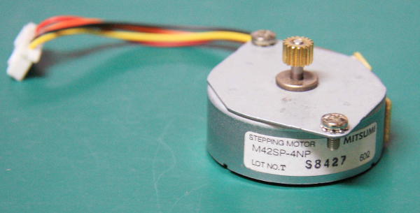
First step motor is Mitsumi M42SP-4NP. Common – Red,W4 – Yellow,W3 – Orange,W2 – Black,W1 – Brown.
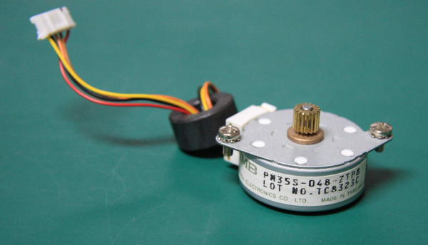
Next is PM35S-048-ZTP8 Minebea Electronics. Common – Red,W4 – Brown,W3 – Yellow,W2 – Black,W1 – Orange.
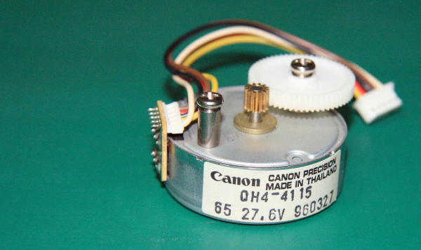
Now for Canon QH4-4115 Stepper Motor. Common – Black,W4 – Red,W3 – White,W2 – Yellow,W1 – Brown.
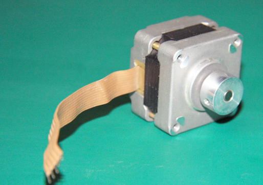
The last motor had no marking, but its wires configuration was the simplest among all tested steppers. If you hold it looking at the back of the motor the first wire from the left is a common followed by W1,W2,W3,W4.
Explore PIC16F category for additional project and designs.