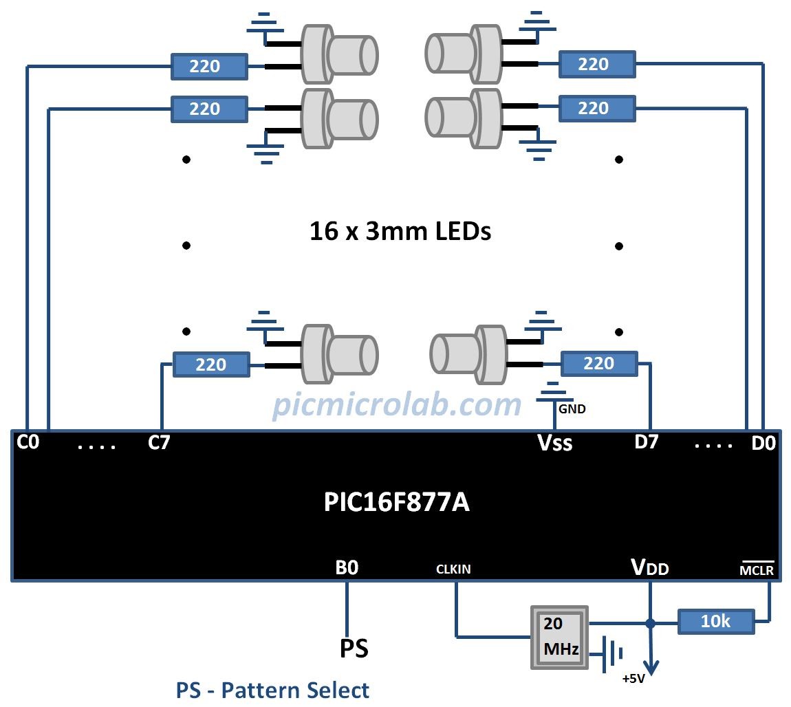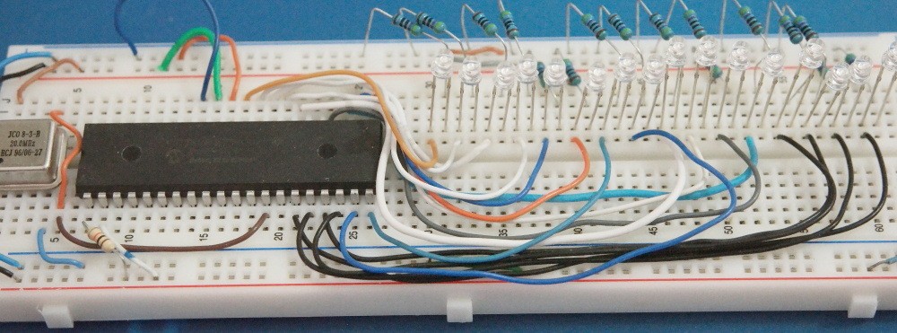
In this post I’ll show a simple running LED circuit. Currently only 2 patterns are available but additional effects can be easily added by slightly modifying the code. This design uses only 16 LED’s however PIC16F877 has 5 I/O ports so more LED’s can be connected. Also the running rate can be controlled by increasing/decreasing the delay loop in the source code. Circuit functionality can be summarized in 2 sentences. PORTS are used to drive the LED’s by sending a predefined set of values to outputs. Repeating this process with high enough rate will create a running light effects on LED’s.If you look at attached assembly source code you’ll see 2 pattern functions named Pattern1_2. These functions are called according to a state of a PS – Pattern Select Input. See design schematic in the next figure. A simple way to add your own lighting effect would be to duplicate one of these functions, rename it and change the numbers being sent to LED’s. Next step is to rebuild the project and program your target device. I’ve used PICkit3 programmer for this purpose. Clear high efficiency 3 mm LED’s are a good choice for this project. Don’t forget to add 250 Ohm resistors to limit the microcontroller output current.