This is PIC16F877A microcontroller based digital clock with 7-Segment display. For this project LTC3710HR was used, however the schematic can be easily adjusted to incorporate larger displays.LTC3710HR
is 0.3 inch quadruple digit multiplex common cathode
display.Main consideration for choosing the display should be current required as PIC outputs can provide about 25mA for each segment. If a higher current is needed you should add transistors to drive the segments.

Time can be adjusted by SW2 – minutes and SW3 – hours. SW4 is used for display test. SW1 is shown but not implemented for now. The code was tested on PIC16LF877A but should work on all PIC16F87X MCU’s with minimal changes. In order to adapt for PIC16F877 just change the following lines in assembly file: LIST P=PIC16F877, include <P16f877.inc>.7 segment inputs are connected to PORTD (bits 0 – 6) through 220 Ohm resistors, PORTC (bits 2-5) are used for multiplexing control and PORTB for outputting the 1 Hz signal and reading the push buttons state. The source code was written in assembly, available at the bottom of the page. Time base of 1 sec is generated from Timer1 interrupt. In the next version of the clock alarm will be added (Should be available in a few weeks).Power supply was built around LM317T Voltage Regulator
(not shown in the schematics), but any other 5v regulator
can be used. Max current measured was about 85mA with all segments ON (SW4 was pushed) in a normal operation ~ 75mA.
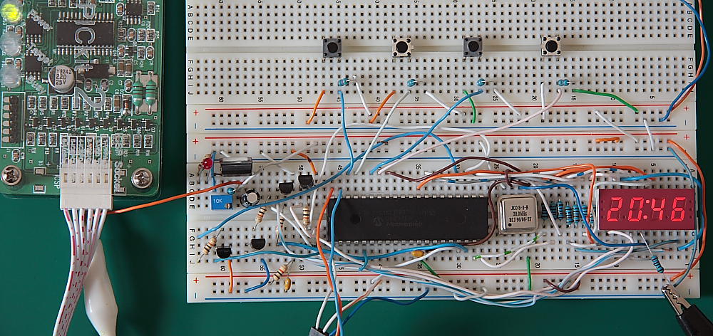
By following provided schematic and code this circuit can be constructed in a few hours. For developing a simple breadboard and Microchip Pickit2
compatible programmer was used for programming the MCU.
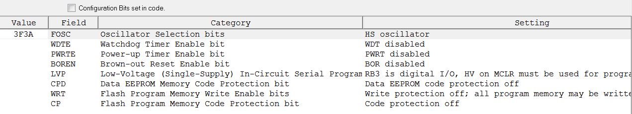
Make sure that configuration bits set correctly in MPLAB (Ver 8.6)