In this post I’m going to show you how to interface an I2C Real Time Clock – RTC with PIC microcontroller. Only a basic hardware configuration and a communication protocol are presented here. I’m planning to extend it to a more advanced design in a near future. Although PCF8573 was used a similar IC’s like PCF8583
will also fit with minimal changes to PIC software. The PCF8573 is a real time clock/calendar IC. Its addresses and data are transferred serially via the two-line bidirectional I2C bus. I2C communication was used in a number of projects like a Function Generator. Here a modified assembly code will read a minutes count from PCF8573 and show its binary value on LED bar graph connected to PORTB of PIC16F876A.
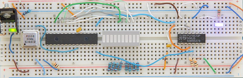
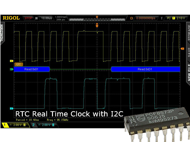
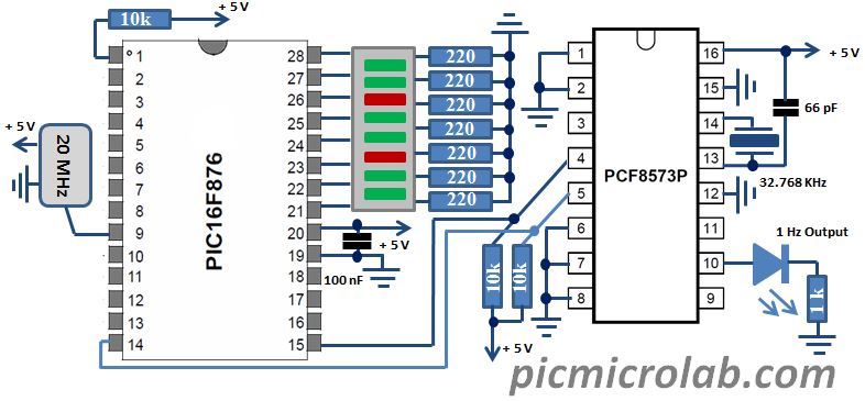
To set up a basic circuit only an oscillator and a small capacitor are required. See design schematic. PCF8573 I2C address 0xD0 is send by PIC. If ACK is received the minutes data is read by sending 0xD1 address and transferred to PORTB. (LSB is R/W bit). More detailed explanation can be found in attached assembly code at the bottom of the page, also look at full Data Sheet for comprehensive functional description of RTC, its timing specification and operation modes. In a screenshot above you can see SCL – Clock and SDA – Data lines while I2C was active. Oscilloscope screen capture was taken with RIGOL DS2072 using its I2C Decoder and trigger mode.
Assembly code is available here. You may also be interested in SPI code example here or UART implementation.