Recently I was asked to build an aquarium lighting controller prototype to provide variable brightness during its operation and ability to program ON/OFF times. 25 blue and white diffused 10mm LED were used to illuminate the aquarium. The main requirement from this design was to gradually increase the LED intensity levels in order not to disturb the fish with sudden changes of illumination. This circuit is based on PIC16F877 microcontroller and uses LM317
with 4 digitally controlled inputs via 4 NPN 2N3904 transistors to modify LED output voltage. Basically the entire design is a modified timer as described in earlier post with addition of voltage controller. LCD display
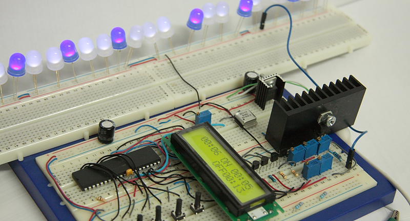
is a standard 2×16 with parallel interface. Its backlighting is constantly ON and is connected to Vcc trough 150 Ohm resistor, see schematic for more details. High resolution picture of the prototype board is available here.Time and Timer ON/OFF settings are done by pressing the relevant push buttons. For example in order to set the Time you’ll need to press Min/Hour adjustment push button while holding down Time button.
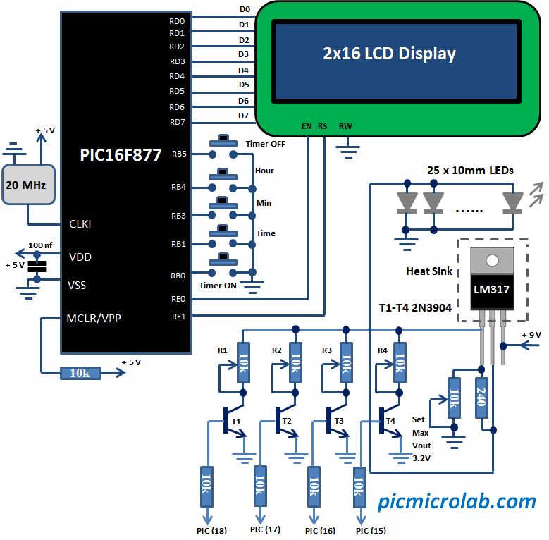 Light intensity grading currently limited to 4 setting, however it can be easily upgraded by adding additional 4 transistor and trimmers to upper bits of PORTC. A backup battery can be added through a diode to Vin to provide power in case of main power outage. Source code is written in Assembly language and can be downloaded here. In my opinion it’s not too complicated to understand and has sufficient amount of comments. Here is a short video demonstrating circuit operation.