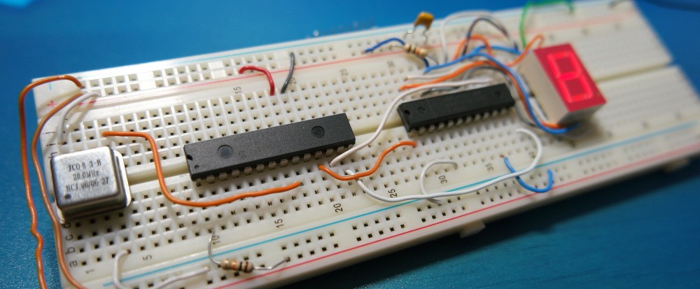
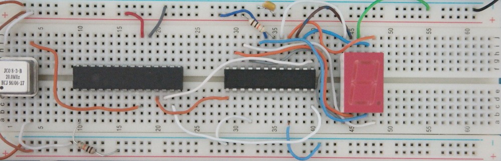
MAX7219 is a common cathode display driver with a simple serial interfaces that can be easily connected to a microcontroller. Among other useful features this IC has built in brightness control and scan control capability that allows to limit the number of shown digits. MAX7219 can drive LED 7 – Segment display up to 8 digits, bar graph or dot matrix display. In this post I’m going to show a basic way to communicate with this device by sending a serial data from PIC microcontroller. Arduino version available at this link. For this specific design PIC16F876 was chosen, however any similar device with 3 available I/O can be used. The code is basically a 16 bit shift register scheme and it uses bits 0,1,2 of PORTC to output 16 bit of data and CLOCK pulses in addition to LOAD output as required by MAX7219 communication protocol. See MAX7219 datasheet for more detailed information. As you can see from the schematic of this circuit it does not have any inputs.
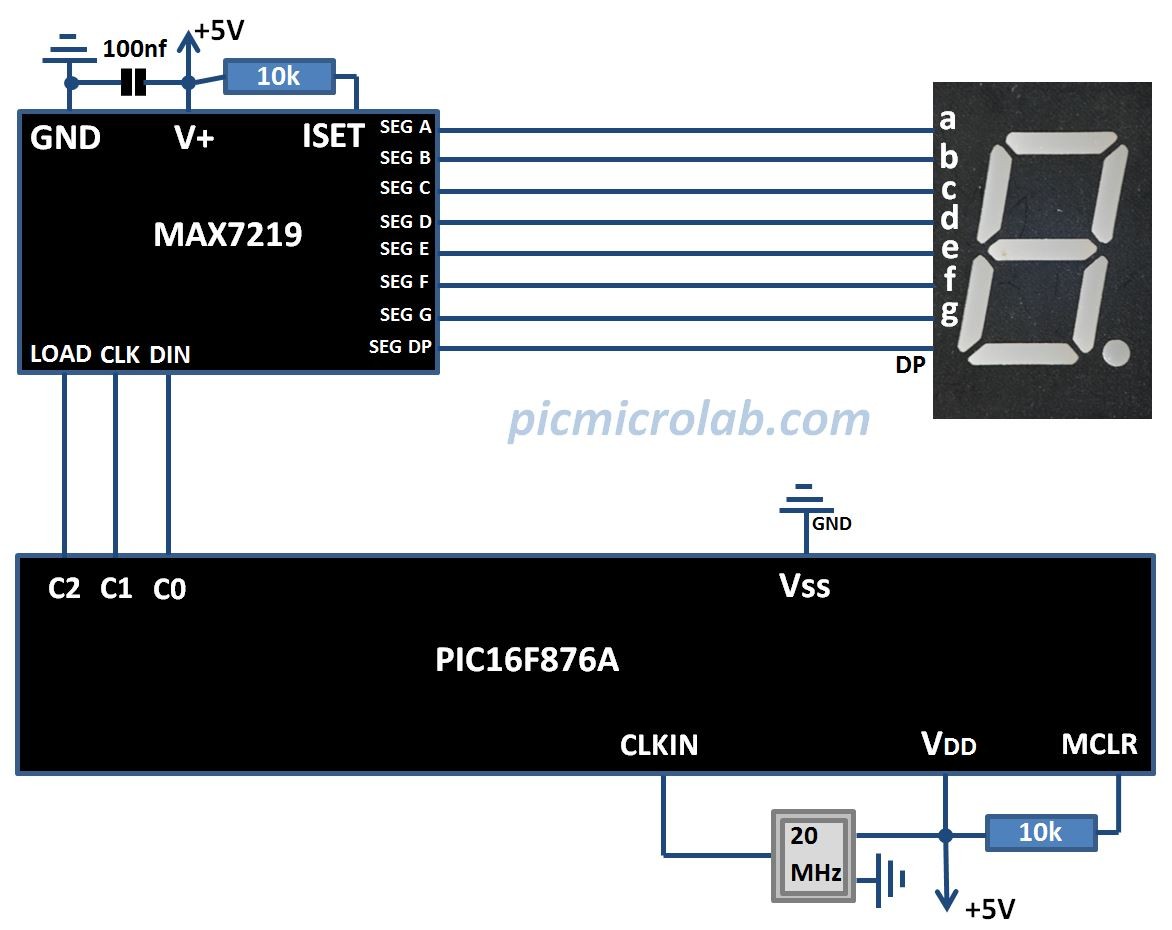
I just wanted to show how to communicate with MAX7219 using a simple function.This function is called SendDataMax7219 and it just sends 2 8bit registers data SendDataH, SendDataL to MAX7219. Current code outputs 10 digits (0-9) every second to MAX7219 in order to produce a simple counter shown on 7-Segment display. See attached assembly code for additional information.
I’m planning to expand this design and add more 7-Segments and to experiment with Dot Matrix Displays. These modules can be purchased on Ebay in different configuration, you just need to connect a microcontroller. Hopefully you can use this design as a basis for more advanced projects.