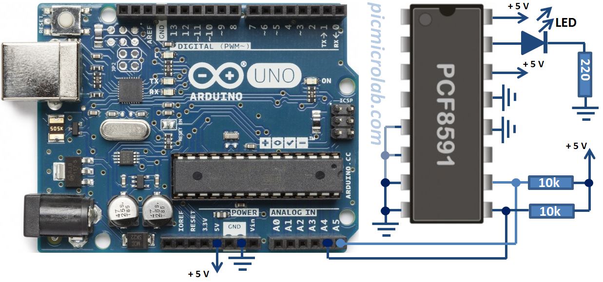
Controlling LED brightness with Arduino is one of the basic circuits you can built. Fade sketch is even included in the basic examples in the Arduino IDE. However on Arduino boards it’s done by pulse width modulation, changing the duty cycle of the signal thus influencing the average voltage on the LED. In this post I’ll show you how you can use PCF8591 DAC/ADC I2C device to perform the same task, but this time you can directly and precisely control the output voltage. For similar design based on PIC micro-controller see this link. Each byte sent to PCF8591 represents a voltage value relative to a Vref .In this example Vref is connected to +5v. Sending 0x00 outputs 0 Volt and 0xff represents MAX voltage of 5 Volts. In the next figure you can see the schematic diagram of this circuit.
 To create fading effect 2 loops were used with a small delay starting from 0 rising to 255 and then decreasing the values from 255 to 0. Arduino code can be downloaded here. You can experiment with initial and final values in these loops to control LED brightness, the time it takes for LED to reach its MAX intensity can also be modified by changing the delay between the loops.
In order to connect high power LED you’ll need to add current boosting transistor at the PCF8591 output. The code used for this simple project should also fit Arduino MEGA or any other compatible boards. Pay attention that SDA and SCL lines on Arduino MEGA are connected to different pins, so a small modification to Arduino sketch is required. Next a short video showing circuit operation is shown. Hopefully you can see changes in LED brightness as a function of output signal duty cycle.