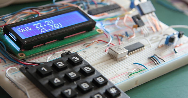
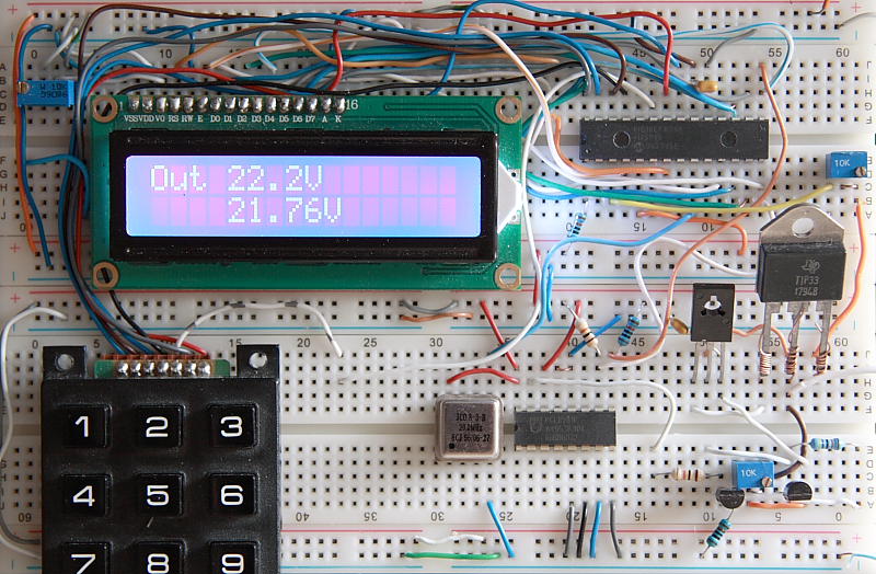
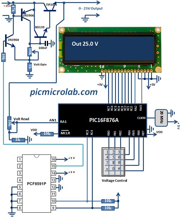
This is an update to a recent post on a subject of building a Digitally Controlled Power Supply. In part 1 a basic configuration was presented. In this version a numbers of modifications were made to software/hardware to produce a more advanced design. The most significant improvements are an increased voltage range and addition of 3×4 keypad to enter output voltage values directly instead of a push button. So now in order to output 25 V you’ll just need to enter 2-5-0. The power output stage stayed almost the same except for a variable resistor was added to allow voltage gain calibration. Enter 255 via keypad and use it to adjust Max voltage to 25.5 Volts. See design prototype board and schematic in the next figures.
Few “bugs” were discovered during the design testing. Keypad scanning routing is too sensitive and sometimes can incorrectly decode the 3 digit value, also analog to digital converter functions update rate is relatively low.Current limiting features still not implemented in this version hopefully it will be done in the next update (Part 3) of this project.
Assembly source code can be downloaded here.