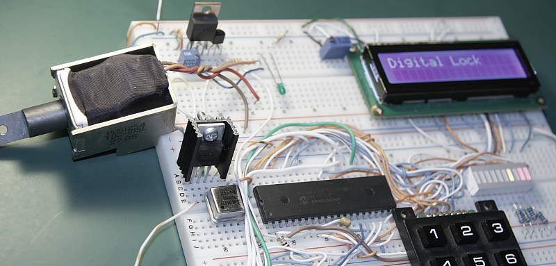
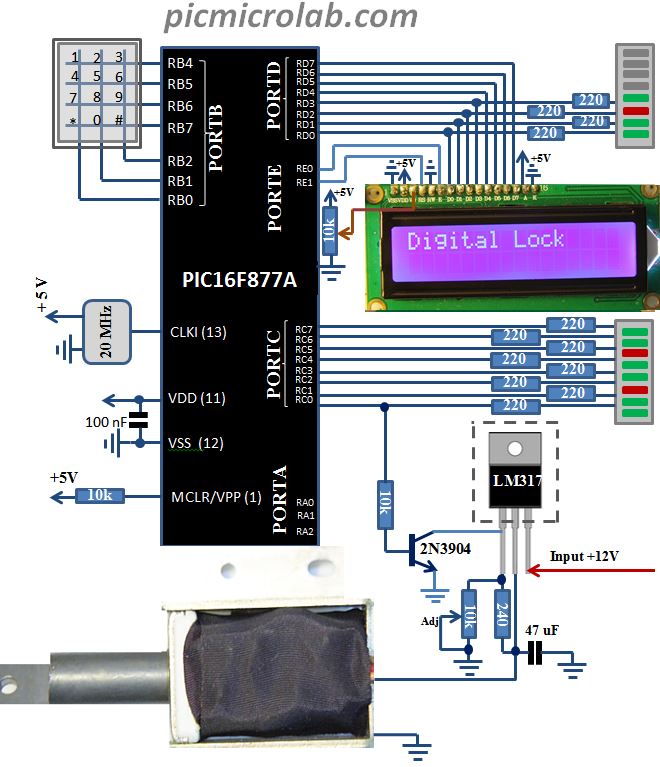
In this post I’m going to show you how to build a simple Digital Lock using PIC microcontroller. Instead of building a new hardware design from scratch we are going to use PIC Development Board as a basis for Digital lock prototyping and testing as it has all the necessary components. Although few modifications are needed, they are relatively simple and easy to implement. We’ll need to add LM317 Voltage Regulator and 2N3904 NPN Transistor to PORTC bit0 to increase output current and to control the load. See design schematic for more details. The only part that is currently missing is a mechanical component of the lock and we are going to simulate its function by controlling a solenoid like TDS-10SL that was dismantled from an old Inkjet Printer. Solenoid can be directly connected to actual door lock thus making it an electronic lock. Should I have some more free time I’ll dedicate it to building such a device. The system will wait for 6 digit code to be entered in correct order to open the lock. The default code is 123456,you can change it by updating Char1-6 variables. Lock security level can be enhanced by introducing a time limit for entering correct combination, for example 1 min or limiting the number of allowed trials.For anyone who wants to test their engineering skills fingertips scanning or some other biometrical identification technics can also be implemented but it’s beyond the scope of this simple design. Few words about the code. Essentially it’s a state machine that scans the keypad while waiting for correct digit sequence to be entered. Lock software is available at the bottom of the page.
Assembly code for Digital Lock is available here. See a short YouTube video demonstrating circuit operation.