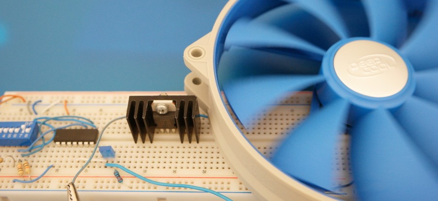
LIST P=PIC16F684
include <P16f684.inc>
__CONFIG _CP_OFF & _WDT_OFF & _BOD_OFF & _PWRTE_OFF & _INTRC_OSC_NOCLKOUT & _CPD_OFF
org 0x00
nop
goto start
org 0x10
start: bcf STATUS,RP0
bcf STATUS,RP1
CLRF T2CON
BSF T2CON,0x0
CLRF CCP1CON ;CCP module OFF
CLRF TMR2 ;Clear Timer2
;——————————————————-
bsf STATUS,RP0
bcf STATUS,RP1
bsf TRISC,0x00 ;Bits 0,1,2 are Inputs
bsf TRISC,0x01
bsf TRISC,0x02
clrf ANSEL ;All ports are Digital
bcf STATUS,RP0
movlw 0x07
movwf CMCON0 ;All ports are Digital
;——————————————————-
loop: MOVLW 0x30 ;Default is High Speed
btfss PORTC,0x00 ;High Fan Speed
MOVLW 0x30
btfss PORTC,0x01 ;Medium Fan Speed
MOVLW 0x15
btfss PORTC,0x02 ;Low Fan Speed
MOVLW 0x10
;——————————————————-
;MOVLW 0x20;0x03 ;0x30 – Duty 97%; 0x01 – Duty < 2%
;High – 0x30 Medium – 0x20 Low – 0x10
PWM: MOVWF CCPR1L ;Duty Cycle
CLRF INTCON ;Disable interrupts, clear T0IF
BSF STATUS,RP0 ;Bank1
MOVLW 0x30;0x09 ;PWM period is 10*4Tosc
MOVWF PR2
BCF TRISC,0x05 ;Make pin 5 Output
CLRF PIE1 ;Disable peripheral interrupts
BCF STATUS,RP0 ;Bank0
CLRF PIR1
MOVLW 0x0C ;PWM mode,2 LSB bits of Duty Cycle=10
MOVWF CCP1CON ;Duty Cycle=1010 =10Tosc
BSF T2CON,TMR2ON;Timer2 starts to increment
GOTO loop
end
On the next page you can get the code and see a short video.
