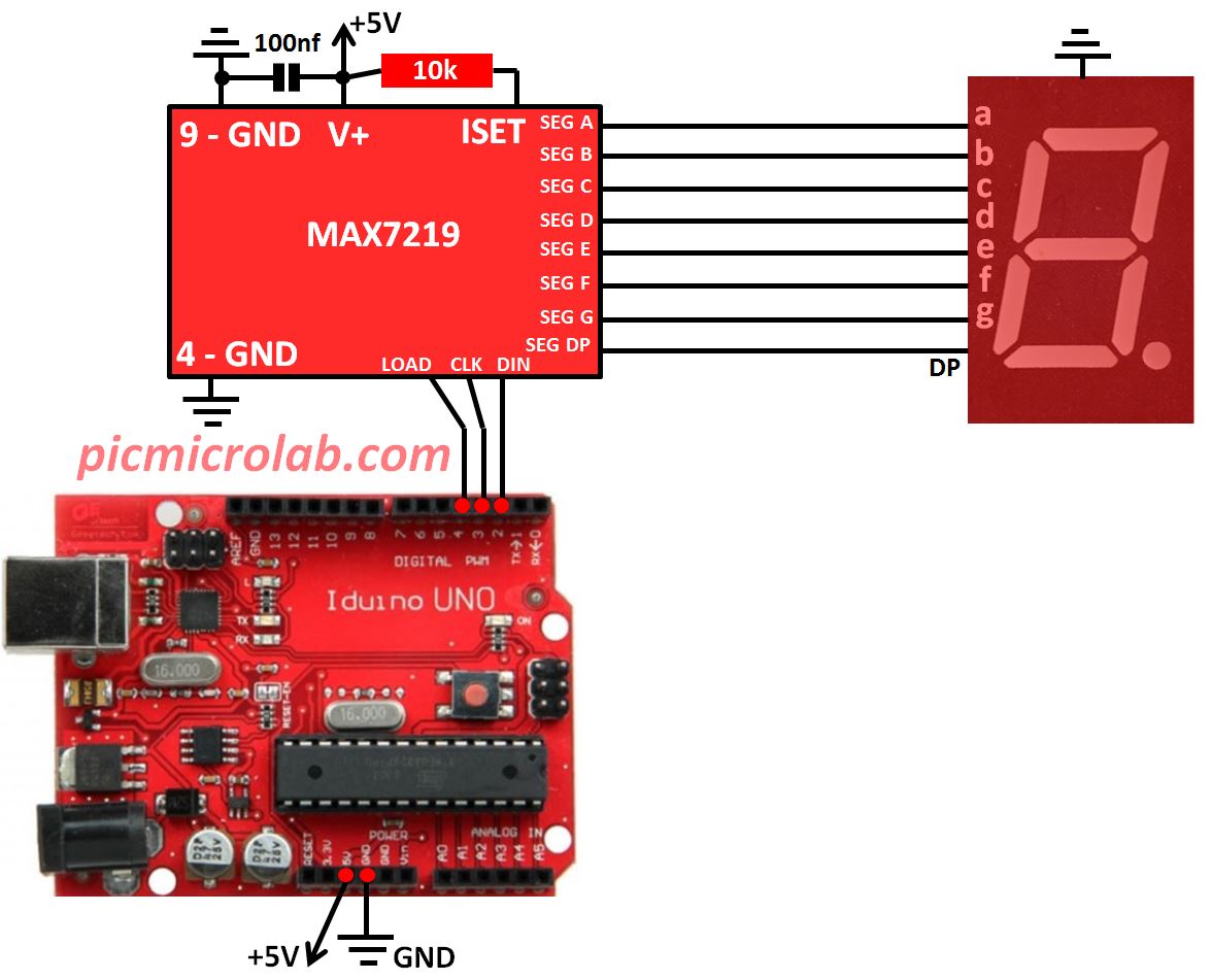
MAX7219 is a serial input/output common-cathode display driver. It can interface the microcontroller to 7-segment numeric LED displays, bar-graph displays, dot matrix display or individual LEDs. This IC has some very useful features like built in decoder, multiplex scan circuitry, segment and digit drivers, and on-chip memory to stores each digit value. Only one external resistor is required to set the segment current for all LEDs. In this post I’ll show you how MAX7219 can be controlled by Arduino. For PIC16F876 example click this link. As you can see from schematic diagram 3 Arduino I/O’s are required to control the chip. MOSI – Master Out Slave In – for outputting the serial data bits, CLK – Clock for correct bit sampling and LOAD to latch the 16 bit number received by the chip.
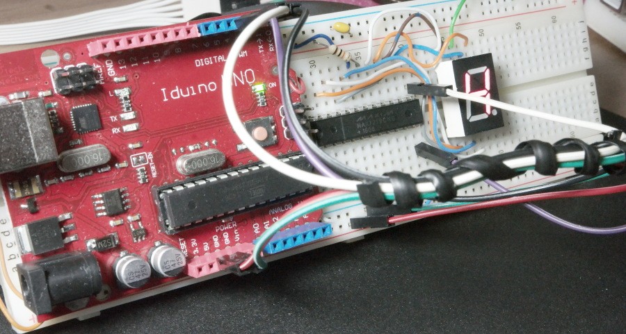
For this design I’ve used Iduino UNO board but any compatible device should also work. Now let’s talk about the code. I’ve written my own interface function named SendDataMax7219. If you look at the attached sketch here you’ll see that this function is a basically a 16 bit shift register with added clock after each bit and a LOAD signal.
MAX7219 needs to be initialized prior to sending data. For example to define the LED brightness and mode of operation. This is done by setup() section in the sketch. Just to show how this function works I made a simple counter, sending digits 0-9 to MAX7219.