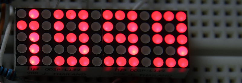
In this post I’ll show you how two QDSP-L149 5×7 dot matrix LED Displays can be used to create a 4 Digit display module. The trick is to change the roles of rows and columns. So now each 5×7 Dot Matrix display can show 2 digits instead of only one.
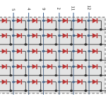
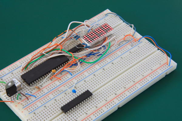
Any other similar 5×7 Dot Matrix Display should work, just verify that right upper dot for each 5×7 unit is connected to RD0,RB0 (columns) and its row to RC0 respectively. You can use attached QDSP-L149 diagram as a reference , otherwise you’ll need to modify the code for your design. The prototype was build on a standard 830 Breadboard. Power supply is a simple 7805 regulator. However if you have PIC16LF877A that can operate with lower voltage 3.3V for example, current limiting resistors at ULN2003 outputs can be omitted, see schematic for additional info. For MCU programming I recommend using programmers like PICKIT2 , PICKIT3. Assembly code for this project is available here.
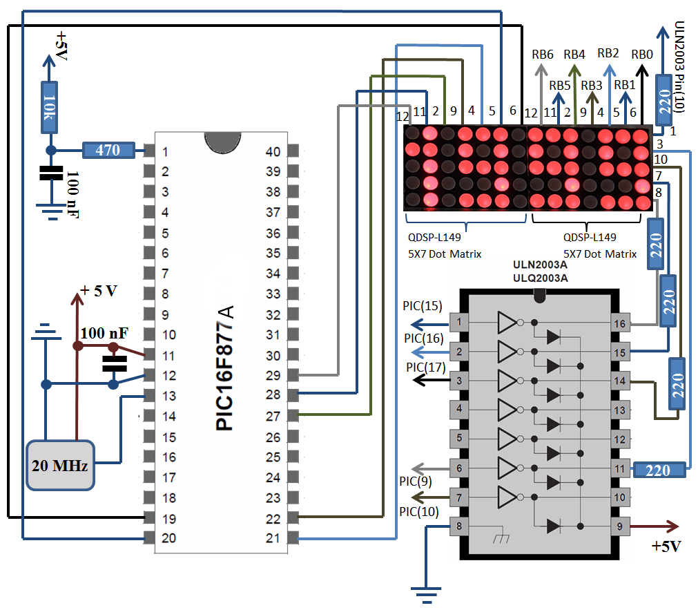
Four PIC16F877A PORTs were used to drive the display. PORTD upper 4 bits controls columns of Digit 4 (MSB) and lower 4 bits Digit 3. PORTB controls columns of Digit 2 and Digit 1.PORTC (RC0-RC2) and PORTE (RE1-RE2) used for row control.ULN2003 is required to deliver the necessary current for two 5×7 Dot Matrix units. The rest of PORTC is not used in this version, giving the option to upgrade the design by adding SPI,I2C or UART functionality in the future. Dot Matrix is similar to LCD, you control every single dot, meaning that you can create and shape your own characters.
Currently the Max reading is 1999 however the code can be easily modified to show more characters, digits and letters. Few additional characters already included in the code, they just commented out for now. In order to display a character you need to enable first row and send 4 bits of data then turn previous row OFF and next row ON and send new 4 bits of information representing part of the character being displayed. Here is the short summary of steps needed in order to drive the display: Put BCD number to convert in 0x25 –> Call BCDtoMatrix5x7 –>converted result in 0x30-0x34 representing 5 rows. 0x30 – Row1, 0x31 – Row2 and so on. Call ShowDigit1,2,3,4 to cycle through the Rows and create an image on the display. Use Microchip PICKIT2 , PICKIT3 Programmers or compatible clones to download the code to microcontroller . Assembly code is here.