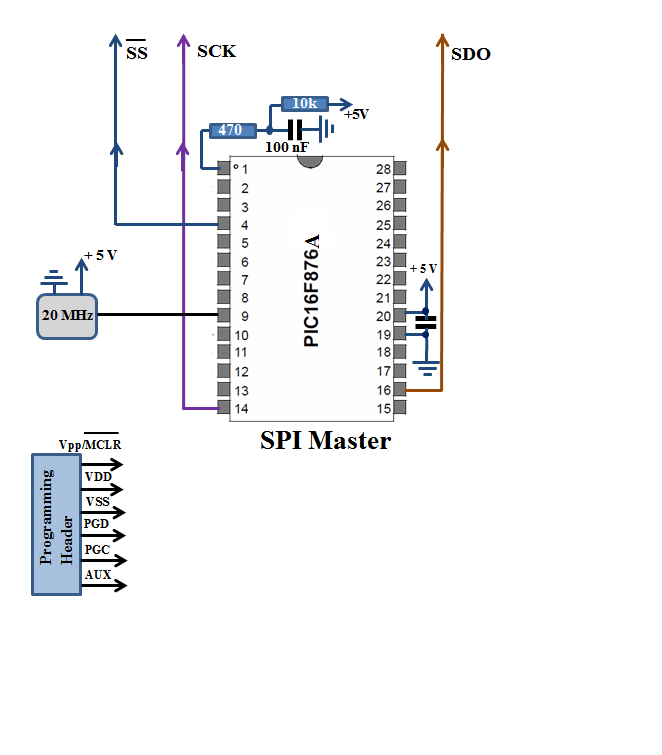
For this project two PIC16F877 MCU’s were used, see project schematics below. Slave PIC runs LEDs decoding and multiplexing code on data received from Master. 7-Segment inputs connected to PORTC,B and common digits anodes to PORTB,A via 2N3906 collectors for current amplification.
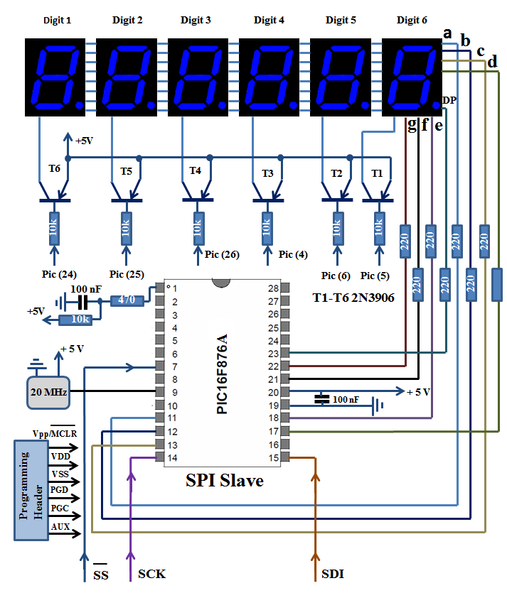
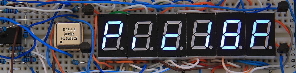
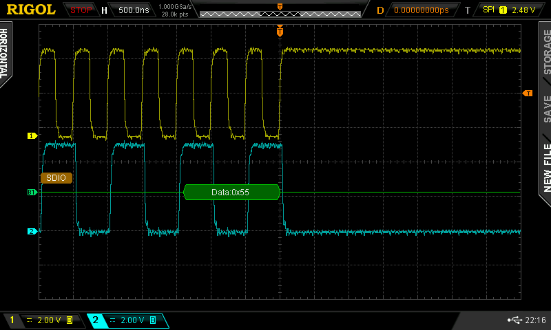
A generic 0.56” Blue Common Anode LED display were used but any other similar components should also work. The project was constructed on two 830 Prototype boards. Get the binary code from Master, call ConvertBCDto7Segment function to convert to 7 segment code, turn relevant segments ON and repeat 5 more times for all 6 digits. Display refresh rate is about 7.5 kHz. More details can be found in assembly code at the bottom of the page. Because common anode segments were used in order to turn the segment ON you need to send “0”. Provided software can be used in 2 ways. If SPI is not required writing binary code to digit address 0x30-0x35 (0x30 Digit1 MSB) will update displayed characters. In order to establish SPI communication Master has to send 0x55 as the first byte followed by 6 bytes for each digit, otherwise Slave will ignore all data received.0x55 can be viewed as Sync or address byte. SPI Master/Slave code was taken and modified from Microchip app notes attached here. Also you can see the scope screen capture of Sync Byte – 0x55 being transmitted by Master with SPI trigger and decoder function enabled. CH1 is Clock (SCK),CH2 is SDO (Data Out)
Currently the following can be shown: 0-9,A,b,c,F,P,i You can modify ConvertBCDto7Segment function in Slave code to obtain additional characters. Both PICs run on 20Mhz clock and SPI was stable on Fosc/4/16/64 frequencies with Fosc = 20Mhz.Possible future improvement/modifications: Adding SPI interrupt instead of pooling will make the code more efficient, also the code can be modified to control each individual digit without sending 6 bytes at once. Any compatible programmer can be used to download the code to the MCU like PICKIT2 or PICKIT3.
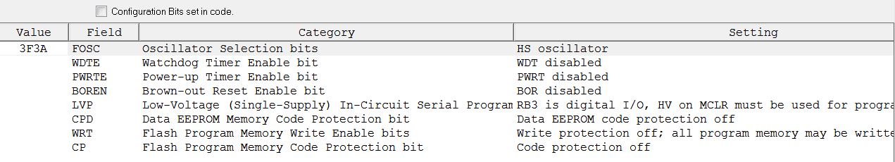
Hex and Assembly Files can be downloaded here. Make sure that configuration bits set correctly in MPLAB (Ver 8.6)