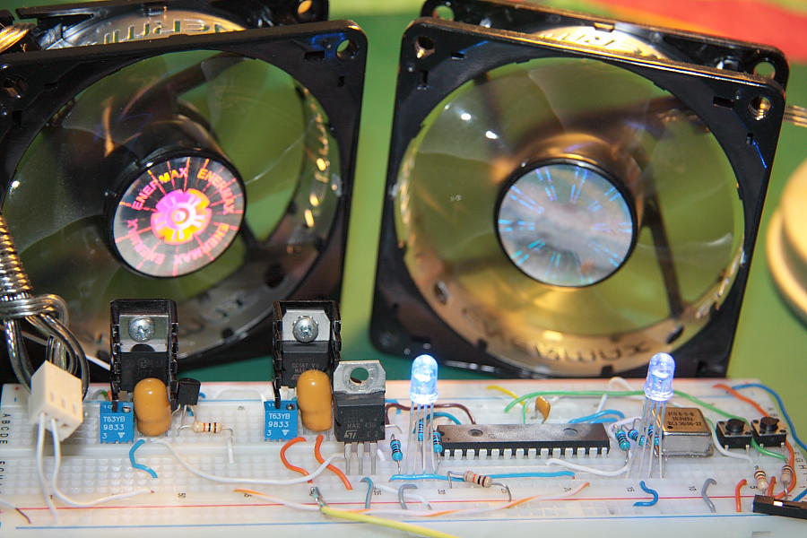
Following recently published article about building a PWM Fan Controller here is another simple controller design. This time it’s a 2 Channel PC Fan Controller for standard 12V Fans. It uses software implementation of PWM but instead of directly driving PWM Fan the output is converted to 3 different voltage setting: High +12V, Medium +10.5V and Low about 9V.Each channel can be individually controlled by two push buttons SW0, SW1.The software is a modified assembly code from Microchip Application notes AN1074 for 12F615 MCU. I’ve changed some configuration settings ,PORTs assignment and added switches scanning routines to adjust it for PIC16F876A.This design was tested with two Enermax UCTB8
12V 0.15A 80mm fans but should work with any standard 12V devices. For simplicity LCD display was omitted, instead RGB LEDs were used to indicate different fan speed: Blue for High speed settings, Red for Medium and Green for Low speed .See attached schematic for more information. Current software version doesn’t use real time fan feedback to monitor its operation and if for some reason the fan should stop working there will be no indication of this event.
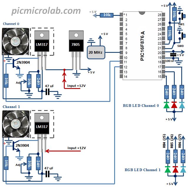
Each channel requires a simple calibration. While in High mode (Max RPM) adjust 10k variable resistor connected to LM317 for 12V output.3 files required to build this project.2 .asm and .h file. Add .asm files to a new project in MPLAB IDE as Source Files. Add .h file to Header Files, build the project. Alternatively you can use included .hex file to program your PIC controller.I’ve used PicKIT3 clone
programmer for this task.Code files available here. See a short YouTube video demonstrating controller operation.