A few weeks ago I’ve uploaded post with relatively simple assembly code example for interfacing 2×16 LCD display with PIC16F microcontrollers
. Driving Graphic LCD display is more complex task as it lacks the build in character generation unit so each pixel needs to be driven individually . As its name implies 128×64 LCD
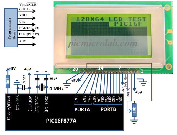
has 128 columns and 64 rows. LCD Module is divided into 2 equal areas/sides – Left side, Right side. Each side consists of 8 rows and 64 columns and controlled by a separate controller. GLCD uses two KS0108 controllers. 2 Controller Select pins – CS1, CS2 used to activate Left or Right Controller. Other pins functionality is similar to 2×16 LCD modules
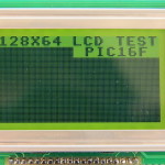
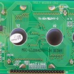
. Data, RS, R/W and Enable perform almost the same. Display model and pin layout are located in the gallery below.
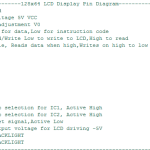
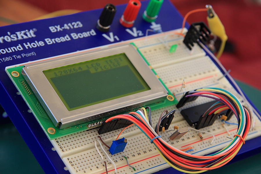
As usual you should check your GLCD Datasheet for correct pin assignment. After spending a few days searching the net for available resource I’ve managed to find this assembly code on one of Microchip forum pages. I’ve only slightly changed the configuration bits for the oscillator and removed few initialization sequences to fit it to PIC16F MCU. The modified working code is available at the bottom of the page. The prototype was built on 1580 Tie Points Breadboard and tested with PIC16F877A
, it seems to work Ok. You can see circuit prototype board here. Similar microcontrollers like PIC16F876A
,PIC16F88
should also work with minimal changes to schematic and code. Any compatible PIC programmer can be used to download the code to microcontroller. I recommend using cheap PicKIT2
or PicKIT3
programmers. See design schematic for programmer header connection. Update 4.21 – Add 10k Pull Down resistors to pins 40,39.Without these resistors the circuit will only work with Programmer attached.
Assembly/hex files can be downloaded here.